21
Electrical connections
3.3
Electrical connections must be established in accordance with the applied standards to
electrical equipment and only by qualified personnel!
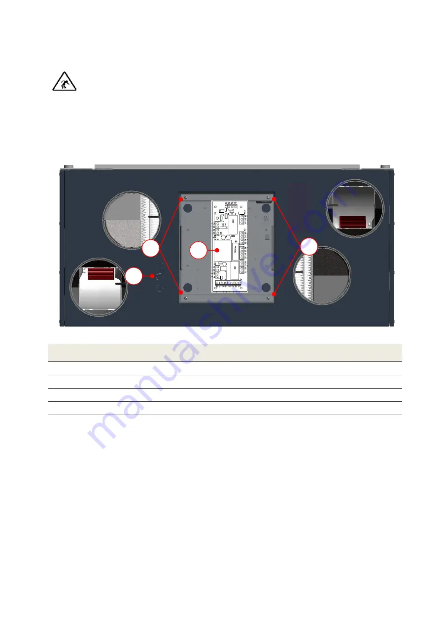
The electric power supply of the FOCUS occurs through the power supply unit with a shockproof plug and
a shockproof 230 Vac socket. The cables to the operating panel and the cable of an optionally
connectible preheater are connected directly to control board
A
. To do this, the 4 screws
B
of the cover
sheet have to loosened and the strands of the cables be connected at the respective terminal points of
the control panel. The cables have to be led through the cable glands M16. The required number of pre-
punched cable bushings
C
has to be broken off.
Fig 23: Surface of the electrical connections
Position
Designation
A
Control board
B
Screw (4x)
C
Pre-cut cable bushing (3x) for cable gland M16
Circiut diagram FOCUS 200 Base
Tab. 4: Assignment of the electrical connections
Connection operating panel
3.3.1
3.3.1.1
Connecting of the connecti
o
n cable to the control panel
The external operating panel is installed in a standardised switch box.
For connecting between the control panel and the control unit an 8-wire UTP data cable 2x4 is
recommended. 4 wires are connected to the terminal points X.01 to X.04 according to Tab. 5.
The maximum cable length is 25 m.
C
B
B
A


