background image

Visuality™ Model T7714 Quick Start Guide

5

4.0  Dock the unit (optional)

Some models of the T7714 are made to fit into a dock in a vehicle designed especially for Visuality models. The 
dock allows you to easily swap remote T7714 units in and out of vehicles. Components for dockable T7714 units 
are the same as standalone units. 
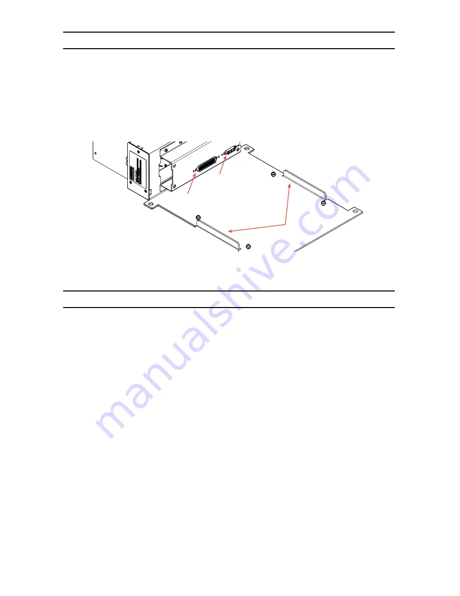
To install a dockable T7714 unit into a dock in a vehicle, line up the T7714 unit with the metal guides on the 
dock. Push the T7714 unit straight back to connect it with the dock. The DB-15 connector installs the GPS and cel-
lular antennas. The DB-78 connector installs the power, video, audio, and other components.

Figure 4. 

T7714 dock

5.0  Log into the unit

You can configure the Model T7714 using the Ethernet port and the Web Management Interface (WMI), or by 
using the Console port and the Command Line Interface (CLI). 
To configure the T7714 using the WMI, make sure that an Ethernet port is connected to the local LAN. Type the IP 
address of the unit into a web browser and log in.
To configure the T7714 using the CLI, connect a PC to the unit’s console port. Open a terminal program on the PC 
and create a connection with the default settings: 19200 baud rate, 8 data bits, no parity, and 1 stop bit.

Note

For information on configuring the unit, refer to the 

Visuality™ Model T7714 User Manual 

and the 

Trin-

ityAE Adiminstrator’s Reference Guide

, available online at www.patton.com/manuals/T7714.pdf and 

www.patton.com/manuals/Trinity-arg.pdf. 

T7714 dock

guides

D-78 connector

for components

DB-15 connector

for antennas

Summary of Contents for Visuality T7714

Page 1: ...Guide The compliance information in this document is incomplete and subject to change IMPORTANT Part Number 07MT7714 QS Rev B Revised March 1 2012 Sales Office 1 301 975 1000 Technical Support 1 301...

Page 2: ...O IN female connector Plug the other end of the BNC cable into the corresponding port on the camera 4 Connect the GPS and cellular antennas Use a SMA cable to connect the GPS and cellular female SMA c...

Page 3: ...ock T7714 Rear Panel Fuse 10A USB2 0 Gigabit Ethernet RJ 45 MainPower TerminalBlock Auxiliary PowerOutput TerminalBlock Pan Tilt Zoom Control DB 9 On Board Diagnostics DB 9 VideotoDisplay BNC Audio to...

Page 4: ...m card The card will eject from the card slot 3 0 Connect power Figure 3 T7714 power connectors To connect the main power 1 Connect the wires for the power connector into the terminal block labeled AC...

Page 5: ...to the unit You can configure the Model T7714 using the Ethernet port and the Web Management Interface WMI or by using the Console port and the Command Line Interface CLI To configure the T7714 using...

Page 6: ...refer to the following documents available online at www patton com manuals Visuality Model T7714 User Manual www patton com manuals T7714 pdf Visuality MVAS Deployment Guide www patton com manuals Vi...

Page 7: ...atton free of charge by using a VoIP ISP phone to call sip support patton com Fax 1 253 663 5693 Alternate Patton support for Europe Middle East and Africa EMEA Telephone support Standard telephone su...

Page 8: ...______________________________________________________ ____________________________________________________________________ ____________________________________________________________________ _______...

Reviews: