background image


IPLink 2800 Quick Start Guide


3


1.3  Models with internal DC power supply


   1.


Strip insulation 1/4-inch from the wires connecting the power source to the IPLink.


   2.


Connect the ground terminal from the power source with to the 


E


 terminal on the IPLink.


   3.


Connect the negative (-) terminal from the power source with to the (


-


) terminal on the IPLink.


   4.


Connect the positive (+) terminal from the power source with to the (


+


) terminal on the IPLink.

The 


PWR


 LED blinks as the IPLink is powering up. When the 


PWR


 LED stops blinking and remains lit, the IPLink is 

ready for user configuration.


2.0  Setting the IP address


2.1  Default IP configuration


The factory default IP settings are as follows:


LAN port(s) (green, ETH 0/1): IP address: 192.168.1.1, netmask: 255.255.255.0


WAN port (red, ETH 0/0): IP address and netmask: DHCP client


A DHCP server with address space 192.168.1.10–192.168.1.99 (netmask: 255.255.255.0) is running on the 
LAN ports


Both Ethernet ports are pre-configured and active

If these addresses conflict or do not match with your network they must be changed. Contact your network 
administrator if you are not sure which IP address to use in your installation.


2.2  Connecting to the PC and logging in


   1.


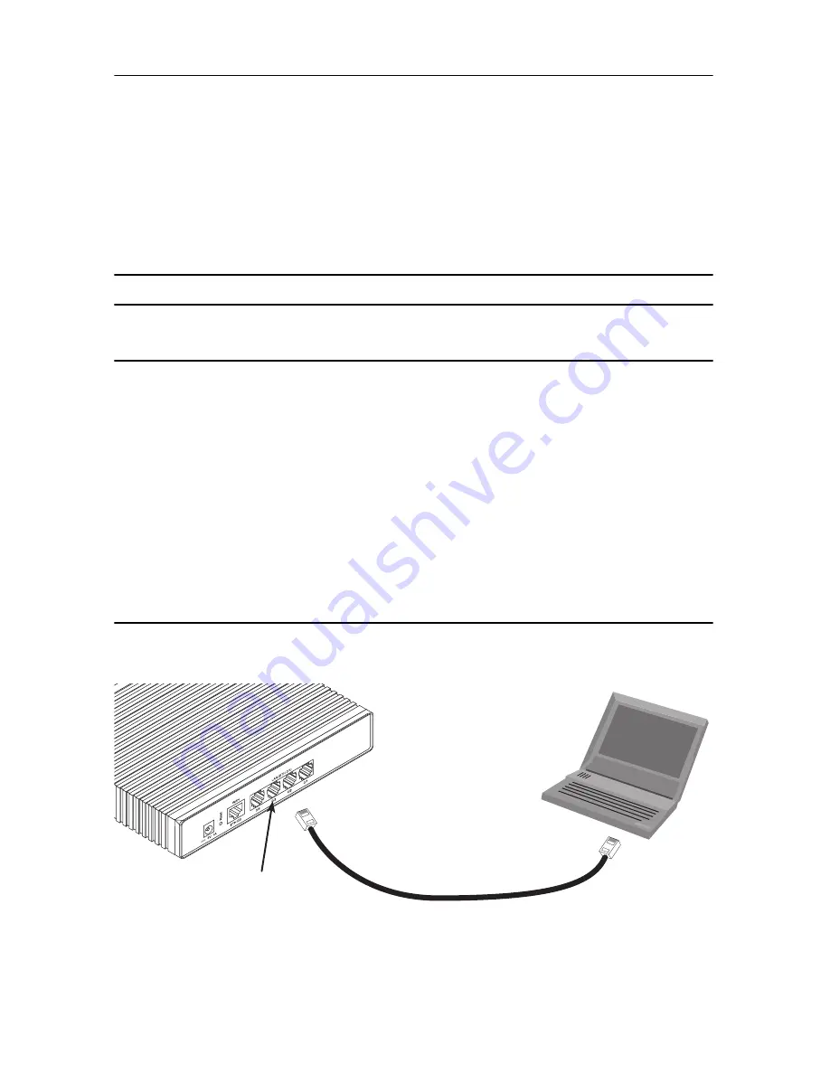
To access the IPLink configuration, connect a PC with an Ethernet port to one of the LAN ports (green) 

(see 


figure 1


). Use the black Ethernet cable included with your IPLink for this purpose. 


Figure 1. 


Connecting to the PC’s ENET port


   2.


Set your PC’s TCP/IP configuration to DHCP to automatically receive an IP address from the IPLink.

PC

(DHCP, for example:

192.168.1.10/24)

Connect to Ethernet LAN

ports 0/1—0/4

IPLink 2800

192.168.1.1/24

Ethernet port

Summary of Contents for IPLINK 2800 series

Page 1: ...es VPN Routers Quick Start Guide Document Number 13220U7 001 Rev D Part Number 07M2800 QS Revised March 31 2006 Sales Office 1 301 975 1000 Technical Support 1 301 975 1007 E mail support patton com WWW www patton com ...

Page 2: ...epairs or repaired by qualified service personnel Mains Voltage Line voltages are present when the power cord is con nected The mains outlet shall be within 10 feet 3 meters of the device shall be easily accessible and protected by a circuit breaker For AC powered units ensure that the power cable used meets all applicable standards for the country in which it is to be installed and that it is con...

Page 3: ...68 1 1 netmask 255 255 255 0 WAN port red ETH 0 0 IP address and netmask DHCP client A DHCP server with address space 192 168 1 10 192 168 1 99 netmask 255 255 255 0 is running on the LAN ports Both Ethernet ports are pre configured and active If these addresses conflict or do not match with your network they must be changed Contact your network administrator if you are not sure which IP address t...

Page 4: ...ixed IP address as follows In this example we assume a private network since the IP address changes to 172 16 1 100 with netmask of 255 255 255 0 1 Select the context IP mode to configure an IP interface 2803 K EUI cfg context ip router 2803 K EUI ctx ip router 2 Set your IP address and network mask on the WAN IP interface eth0 Contact your network administra tor if you are not sure what IP addres...

Page 5: ... patton com 4 0 Connecting the IPLink serial port If your IPLink is equipped with a serial WAN port connect it to the appropriate DCE The IPLink 2800 Series is available with the following serial interfaces V 35 DB 25 Model 2835 X 21 DB 15 Model 2821 E1 RJ48C or dual coaxial connectors Model 2803 K T1 RJ48C Model 2803 T For the V 35 and X 21 serial ports do the following to connect the serial cabl...

Page 6: ...o coaxial connectors on the rear of the IPLink If two coaxial cables plug the coaxial cables into the RX and TX connectors on the rear of the IPLink The RX is an input and the TX is an output 2 The T1 E1 port default is disabled Enable the T1 E1 port 2803 K EUI if ip eth0 exit 2803 K EUI ctx ip router exit 2803 K EUI cfg port e1t1 0 0 2803 K EUI prt e1t1 0 0 no shutdown 2803 K EUI prt e1t1 0 0 sho...

Page 7: ...s relating to Radio and Telecommunication Terminal Equip ment and the mutual recognition of their conformity The safety advice in the documentation accompanying this product shall be obeyed The conformity to the above directive is indicated by the CE sign on the device The signed Declaration of Conformity can be downloaded from www patton com certifications The safety advises in the documentation ...

Page 8: ...5 1007 Support via VoIP Contact Patton free of charge by using a VoIP ISP phone to call sip support patton com Fax 1 253 663 5693 Alternate Patton support for Europe Middle East and Africa EMEA Telephone support Standard telephone support is available five days a week from 8 00 am to 5 00 pm CET 0900 to 1800 UTC GMT by calling 41 0 31 985 25 55 Fax 41 0 31 985 25 26 Note For additional service and...

Reviews: