


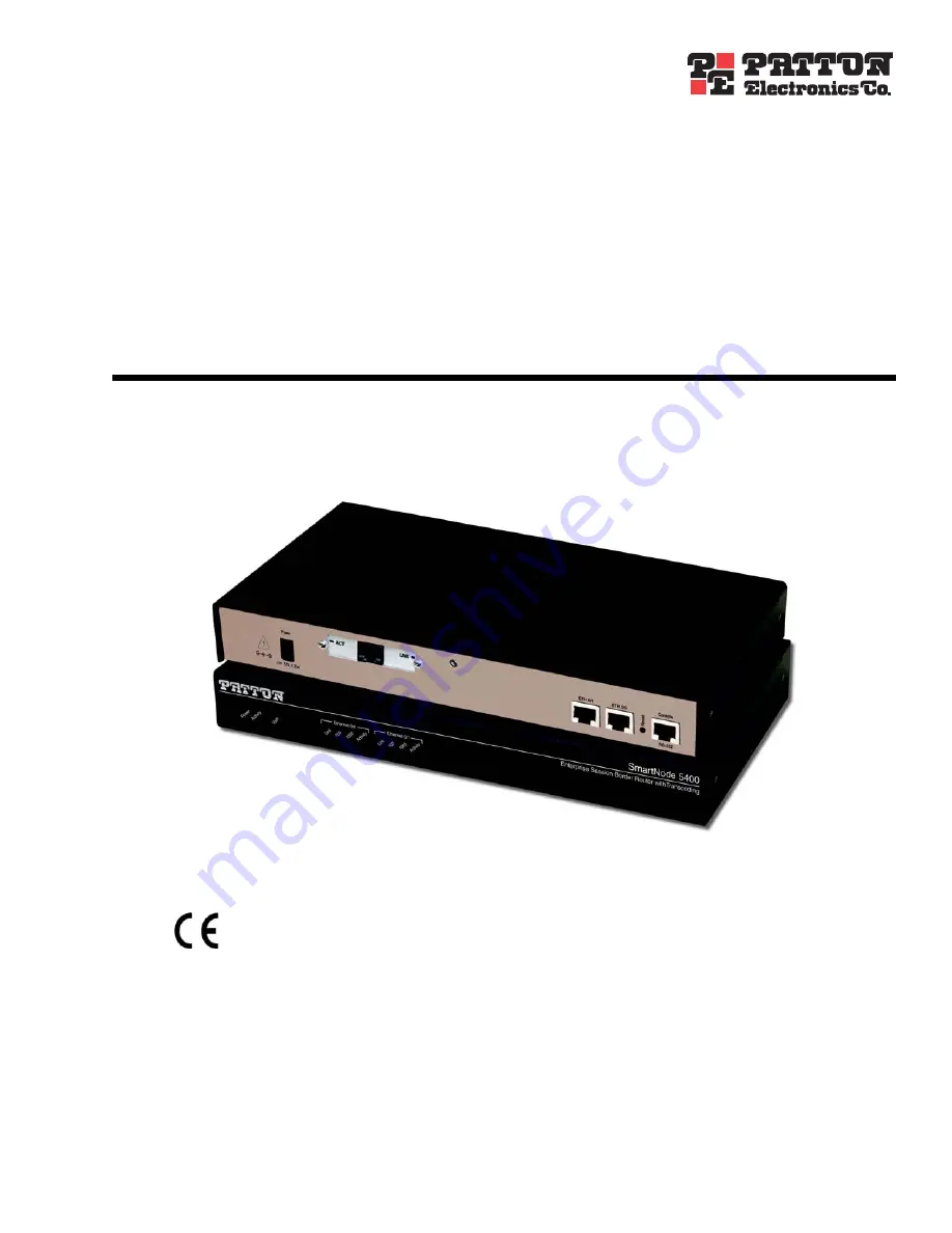
SmartNode 5400 Series
Enterprise Session Border Router
Getting Started Guide
Sales Office:
+1 (301) 975-1000
Technical Support:
+1 (301) 975-1007
E-mail:
WWW:
www.patton.com
Part Number:
07MSN5400-GS, Rev. A
Revised:
December 9, 2010
Important
This is a Class A device and is not intended for use in a residential environment.
Start Installation
For Quick


