background image

5

6

33..00 


C

CO

ON

NFFIIG

GU

UR

RA

ATTIIO

ON

N

This section describes the location and orientation of the Model

1094ARC’s configuration switches and jumpers, and provides detailed
instructions for all possible settings. 

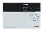
3.1  CONFIGURING THE HARDWARE SWITCHES

The Model 1094ARC Series front card uses hardware switches for

configuration. There is an  interface driver board strap, and three eight-
position DIP switches, on the bottom side of the front card (see Figure
1, below).  

Figure 2 shows the orientation of the DIP switches with respect to

the “ON” and “OFF” positions.

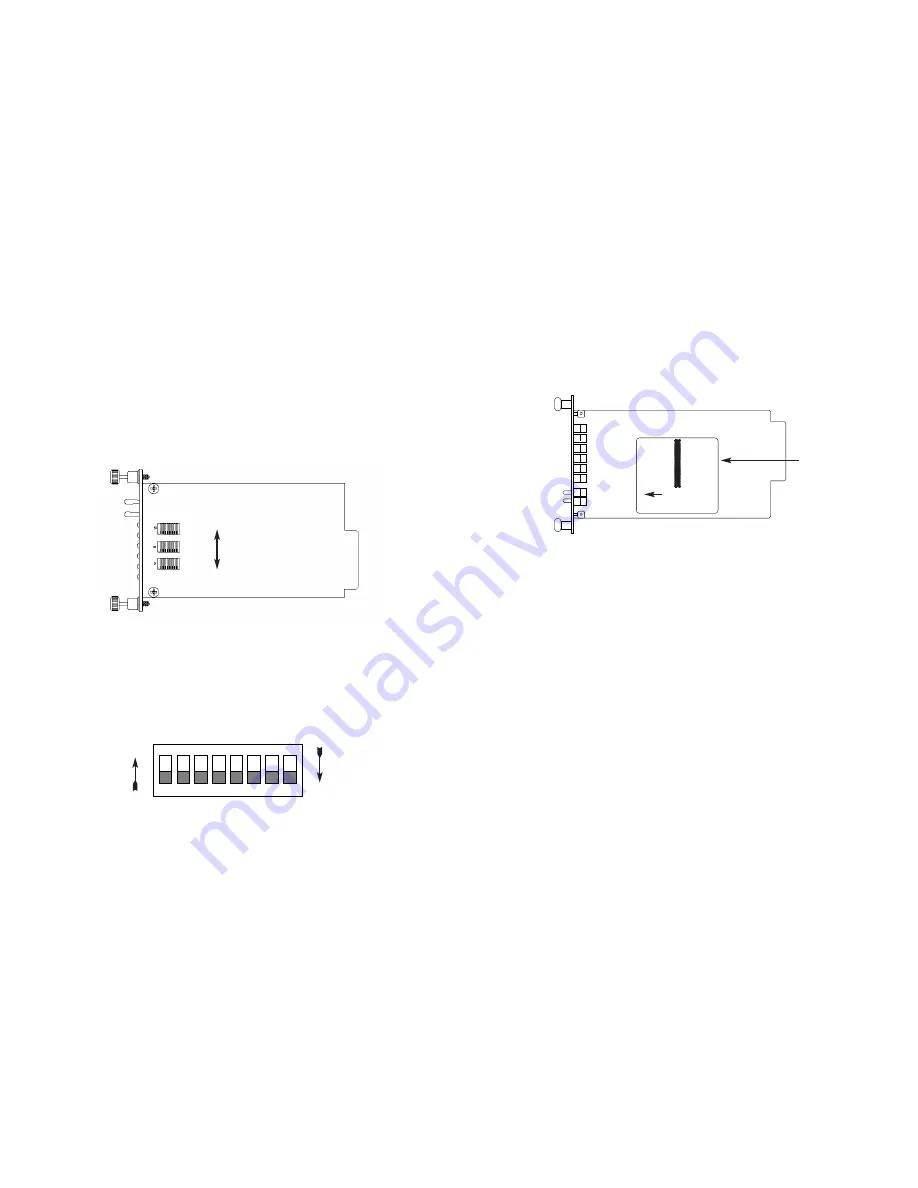
3.1.1  Reversible Interface Driver Board

The Model 1094ARC Series features switchable interface driver

boards that allow a wide range of DTE interface connections. Figure 3
shows the Interface Driver Board on the top of the 1094ARC PC
board. 

Follow the instructions below to select the correct interface for your
application:

1.   With the 1094ARC front card pulled out of the rack or cluster-

box chassis, locate the driver board on the top of the
1094ARC front card.

2.   Lift the interface board gently off of the PC board.

3.   Locate the correct interface on the bottom of the driver board.

For example, the RS-232/V.35 interface board is marked
“THIS SIDE UP FOR RS-232” on one side and “THIS SIDE
UP FOR V.35” 
on the other side Other “single” interface
boards are marked with “FRONT” on one side of the board.

4.   Re-orient the interface board into the socket with the appropri-

ate interface pointed UP and with the arrow pointing toward
the front panel of the Model 1094ARC PC board.

5.   Push the Interface Driver Board gently onto the socket and re-

install into the rack or cluster system.

Figure 1.  Model 1094ARC, showing configuration switches and interface board

Figure 2.  Close up of configuration switches (both sets are identical in appearance) 

1

2

3

4

5

6

7

8

ON

OFF

ON

SW3

SW2

SW1

ON      

OFF

Figure 3. Closeup of Top Side of Model 1094ARC Interface Driver Board

ON

12345678

ON

12345678

Interface
Driver
Board

FRONT

THIS SIDE UP FOR V.35

Summary of Contents for NetLink 1094ARC

Page 1: ...SL Symmetric DSL Rack Mount Modem Card SALES OFFICE 301 975 1000 TECHNICAL SUPPORT 301 975 1007 http www patton com Part 07M1094ARC A Doc 032052UA Revised 06 24 99 C E R T I F I E D An ISO 9001 Certif...

Page 2: ...incurred by the use of this product These damages include but are not limited to the following lost profits lost savings and incidental or consequen tial damages arising from the use of or inability t...

Page 3: ...s LED indicators for TD RD CTS CD DTR TM ER and NS 2 2 DESCRIPTION The Patton Electronics NetLinkTM HDSL Model 1094ARC Multi Rate DSL Modem provides high speed 2 wire connectivity to ISPs PTTs and cor...

Page 4: ...the 1094ARC front card pulled out of the rack or cluster box chassis locate the driver board on the top of the 1094ARC front card 2 Lift the interface board gently off of the PC board 3 Locate the cor...

Page 5: ...s wired as a DCE Reverse the DCE DTE orientation by pulling the strap out of its socket rotating it 180 then plugging the strap back into the socket You will see that the DCE DTE arrows now point in t...

Page 6: ...kbps Off Off On On On On 64 On On Off On On On 128 Off On Off On On On 192 On Off Off On On On 256 Off Off Off On On On 320 On On On Off On On 384 Off On On Off On On 448 On Off On Off On On 512 Off...

Page 7: ...CM134TB M 34 TB the Model 1001RCM11545 and the Model 1001RCM115TB Each of these options supports one DTE interface connection and one 2 wire line connection Figure 4 below illustrates the six differen...

Page 8: ...ce strap functions for the rear interface cards Following the table overview are detailed descriptions of each strap s function DTE Shield DB 25 Pin 1 FRGND JB3 In the connected position this strap li...

Page 9: ...rom frame ground JB4 Position 1 2 SGND and FRGND Connected Position 2 3 SGND and FRGND Not Connected 3 2 3 Model 1001RCM11545 1001RCM115TB Strap Settings Figure 8 shows strap locations for the Model 1...

Page 10: ...interface 4 1 THE MODEL 1001R14 RACK CHASSIS The Model 1001R14 Rack Chassis Figure 9 below has fourteen short range modem card slots plus its own power supply Measuring only 3 5 high the Model 1001R14...

Page 11: ...2 wire twist ed pair port For specific interface pin outs refer to the diagrams in Appendix C and E of this manual 4 3 1 Connection to the Twisted Pair Interface The Model 1094ARC supports communicati...

Page 12: ...l location of each LED Following Figure 10 is a description of each LEDs function TD RD glows yellow to indicate an idle condition of Binary 1 data on the respective terminal interface signals Green i...

Page 13: ...normal operation the framer transmits and expects to receive framed packets from the far end If the framer receives framed packets from the far end CTS and CD will be active If framed packets are not...

Page 14: ...ther by the front panel switch or the DTE interface the unit will enter mode 1 If the units are linked NS LED off then the unit will enter a mode 2 Local Loop A Mode 1 Local Loop is shown in Figure 13...

Page 15: ...estart the box After the 511 511E pattern times out the ER led will begin flashing Local Loop It will remain this way until the pattern generator with 511 511E switch is turned off Note that the data...

Page 16: ...thrown again before the completion of the termination phase the switch will be ignored until it is placed back into the normal position Figure 17 Block Diagram Remote Loop Remote Digital The Remote Di...

Page 17: ...tes the test Figure 19 Block Diagram DataMode with 511 511E 5 2 3 Using the V 52 BER Test Pattern Generator To use the V 52 BER tests in conjunction with the Remote Digital Loopback tests or with Loca...

Page 18: ...TTON ELECTRONICS MODEL 1094ARC FACTORY REPLACEMENT PARTS AND ACCESSORIES Patton Model Description 1001RPEM RAC 120 240V Rear Power Entry Module 1001RPSM RUI 120 240V Front Power Supply Module 1001RPEM...

Page 19: ...AP PP PE EN ND DI IX X C C PATTON ELECTRONICS MODEL 1094ARC TERMINAL INTERFACE PIN ASSIGNMENTS Continued RS 232 RS 530 Interface Pin Description DB 25 Female Connector DCE Configuration Pin Signal 1...

Page 20: ...8 20700 3 9 6 2 24500 4 6 7 3 272 192 256 17400 3 3 5 2 24200 4 5 7 2 400 320 384 15100 2 9 4 6 22600 4 2 6 7 528 448 512 14900 2 8 4 4 21000 3 9 6 2 784 576 640 704 768 13500 2 6 4 2 18000 3 4 5 4 10...

Page 21: ...RC LINE INTERFACE PIN ASSIGNMENTS RJ45 Connector Pin Number Signal 1 N C No Connection 2 N C No Connection 3 N C No Connection 4 Tip 5 Ring 6 N C No Connection 7 N C No Connection 8 N C No Connection...

Reviews: