background image


Connecting to the USB, Speaker/Earphone and Internet/Intranet


15


NanoServ™ User Manual 


3 • Peripherals


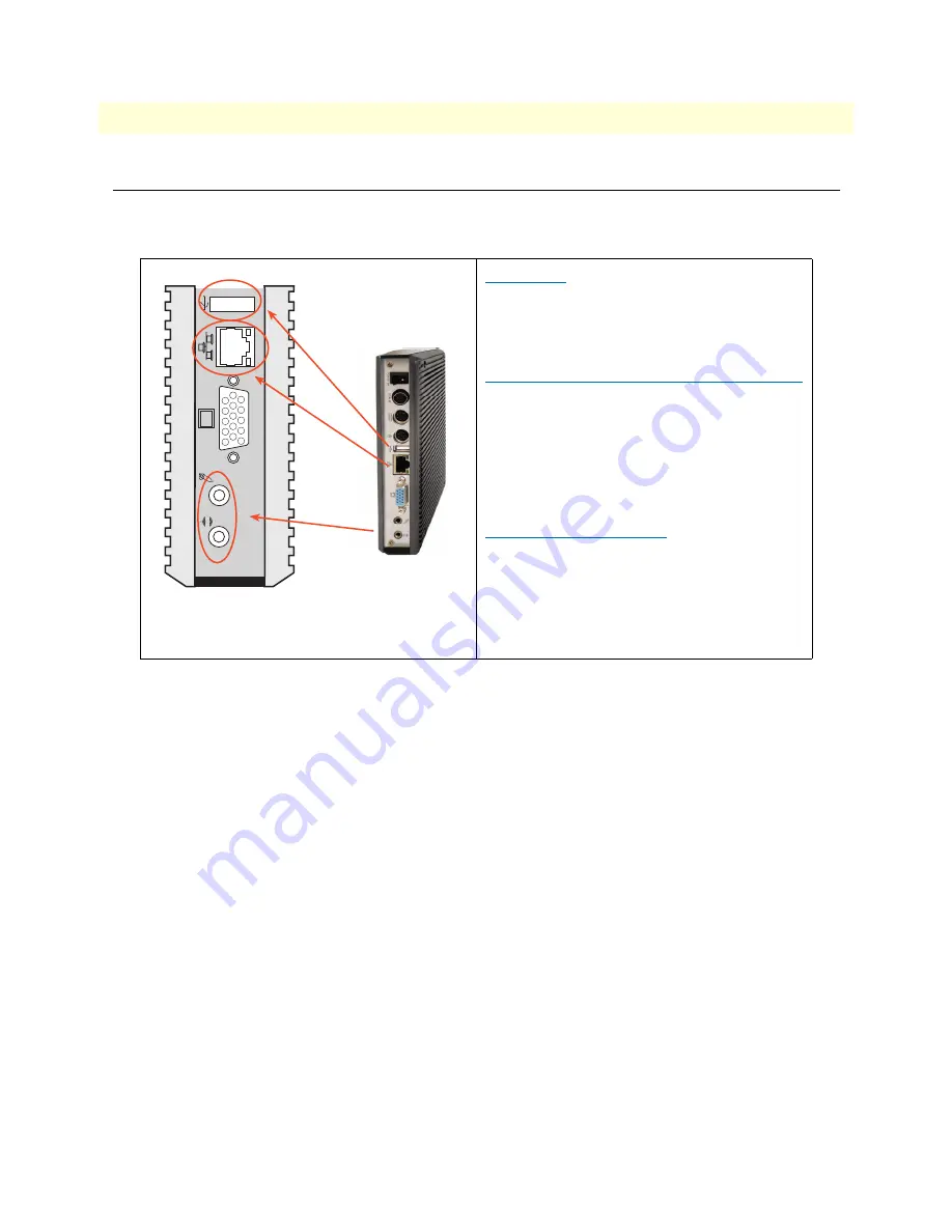
Connecting to the USB, Speaker/Earphone and Internet/Intranet


*Note: Speaker/Earphone/Microphone not included.*


Table 4. Connecting the USB, Speaker/Earphone and Internet/Intranet


USB Port


The second USB port is available on the back 
of the unit for connecting USB devices.


Connecting to the Internet/Intranet


There is an available RJ-45 10/100 Ethernet 
jack for connection to the hub of your intranet; 
and via your server for internet service (see the 
diagram for the RJ-45 10/100 Ethernet jack on 


page 40


).


Speaker/Earphone


The NanoServ™ supports Input/Output con-
nections for a speaker, earphone and MIC 
(microphone). Note that there is a third audio 
jack on the inside by the pin header. The extra 
small cable for this is optional.

{

Summary of Contents for NanoServ

Page 1: ...System User Manual Sales Office 1 301 975 1000 Technical Support 1 301 975 1007 E mail support patton com WWW www patton com Document Number 09407U2 001 Rev A Part Number 07M6070 UM Revised August 2 2...

Page 2: ...ithout prior written permission of the fac tory Special Note To Users THE FACTORY PROVIDES NO WARRANTY WITH REGARD TO THIS MANUAL THE SOFTWARE OR OTHER INFORMATION CONTAINED HEREIN AND HEREBY EXPRESSL...

Page 3: ...install your NanoServ in wet locations To avoid electrical shock do not open the case Contact the factory offices for qualified personnel servicing Never touch un insulated terminals or wire unless yo...

Page 4: ...ct or disconnect cables during periods of lightning activity In accordance with the requirements of council directive 2002 96 EC on Waste of Electrical and Electronic Equipment WEEE ensure that at end...

Page 5: ...the power adaptor 18 4 BIOS 19 Reconfiguring the system 20 5 Taking Care Of Your NanoServ 21 Storing 22 Using cables for connection 23 Cleaning your NanoServ 23 6 Troubleshooting 24 Troubleshooting y...

Page 6: ...ications 32 Compliance 33 EMC 33 Safety 33 Radio and TV interference 33 CE Declaration of Conformity 33 System Specifications 34 Technical Specifications 35 Model Numbers 36 C NanoServ System Connecto...

Page 7: ...are not included in the system Table 1 Packing list Item Description Quantity 1 NanoServ system computer x1 2 Max 25 watts External Power Adaptor Vin 100 240VAC a 60 50Hz 1 0A Vout 5 0 5 25VDC 4A max...

Page 8: ...8 Chapter 1 General Information Chapter contents NanoServ System Overview 8...

Page 9: ...very little space on the corner of a table The NanoServ can also serve as an Internet Appliance that offers state of art design for networking com puting transaction and information transport applica...

Page 10: ...10 Chapter 2 NanoServ System Overview Chapter contents Ultra Thin System Overview 10 Thin System Overview 11...

Page 11: ...D LED flashes when the system is working Please do not turn off the system when HDD starts running Power Switch Depress the switch to turn on and turn off the system USB Port The USB port is for a con...

Page 12: ...not turn off the system when HDD starts running Power Switch Depress the switch to turn on and turn off the system USB Port The USB port is for a connection to external devices with a USB interface k...

Page 13: ...ntents Introduction 13 Connecting the monitor 13 Connecting the USB 13 Connecting to the USB Speaker Earphone and Internet Intranet 14 Connecting the keyboard and mouse 15 Connecting the Printer Port...

Page 14: ...e Interconnecting cables shall be acceptable for external use and shall be rated for the proper application with respect to voltage current anticipated temperature flammability and mechanical servicea...

Page 15: ...lable on the back of the unit for connecting USB devices Connecting to the Internet Intranet There is an available RJ 45 10 100 Ethernet jack for connection to the hub of your intranet and via your se...

Page 16: ...sition Click Press the left button once Double click Press the left button twice Right click Press the right button once When selecting most pro grams this action displays a shortcut menu Scroll wheel...

Page 17: ...erv User Manual 3 Peripherals Connecting the Printer Port Table 6 Connecting the printer port Printer port The DB 25 printer port is available on the back of the thin system unit It is used for connec...

Page 18: ...r switch supplies power to the NanoServ Table 7 Connecting the power adaptor Power Adaptor To use your NanoServ immediately use the supplied AC adapter as a power source See the diagram on the left Co...

Page 19: ...19 Chapter 4 BIOS Chapter contents Reconfiguring the system 21...

Page 20: ...configure the NanoServ depress or hit the Del key to enter your BIOS setup main menu 2 Select a setup from the menu 3 Press Esc to go back to the main menu 4 Move your cursor to Save Settings and Exit...

Page 21: ...21 Chapter 5 Taking Care Of Your NanoServ Chapter contents Storing 21 Using cables for connection 22 Cleaning your NanoServ 22...

Page 22: ...nternal buildup of heat Do not place your NanoServ near the wall behind the curtains or draperies or in between two books that block its venti lation slots Leave a space of at least 8 inches 20cm arou...

Page 23: ...etergent solu tion Do not use any type of abrasive pad scouring powder or solvent such as alcohol or benzine as these may damage the finish of your NanoServ When a solid object falls or a liquid spill...

Page 24: ...24 Chapter 6 Troubleshooting Chapter contents Troubleshooting your system 24 A The NanoServ does not start 24 B BIOS Error Message 24 C Operating System Not Found 25...

Page 25: ...the power connection before pressing the power button Condensation may cause the NanoServ to malfunction for awhile If this happens do not use the NanoServ for at least one hour after the condensatio...

Page 26: ...indows still does not start follow these steps to initialize the BIOS 1 Turn off the NanoServ 2 Remove any peripheral devices connected to the NanoServ 3 Restart the NanoServ 4 Press DEL to enter BIOS...

Page 27: ...n support headquarters in the USA 34 Alternate Patton support for Europe Middle East and Africa EMEA 34 Warranty Service and Returned Merchandise Authorizations RMAs 34 Warranty coverage 34 Out of war...

Page 28: ...3 663 5693 Alternate Patton support for Europe Middle East and Africa EMEA Online support available at www patton inalp com E mail support e mail sent to support patton inalp com will be answered with...

Page 29: ...issued upon receipt and inspection of the equipment 30 to 60 days We will add a 20 restocking charge crediting your account with 80 of the purchase price Over 60 days Products will be accepted for rep...

Page 30: ...30 Appendix A Factory Defaults Chapter contents BIOS Defaults 30 Fedora Core 5 Install Defaults 30...

Page 31: ...ed on NanoServ Model 6075 1 Language English 2 Keyboard U S English 3 Partitioning 1 Ext3 partition at boot at 100MB set as primary partition 2 Swap partition at 1 5 times RAM 768MB min 3 Ext3 partiti...

Page 32: ...ppendix B Specifications Chapter contents Compliance 32 EMC 32 Safety 32 Radio and TV interference 32 CE Declaration of Conformity 32 System Specifications 33 Technical Specifications 34 Model Numbers...

Page 33: ...in a particular installation If the equipment causes interference to radio or television reception which can be determined by disconnecting the cables try to correct the interference by one or more o...

Page 34: ...Keyboard Port PS 2 Mouse Port On Board IDE Bus Master Ultra DMA 66 operation Can connect to 2 IDE devices Peripheral 1 Printer port x1 support SPP EPP ECP module a 2 USB2 0 ports x2 3 Serial port x1...

Page 35: ...front Display Chipset Integrated VIA Uni Chrome 2D 3D Graphics with MPEG2 Accelerator Display Memory 8 MB shared system memory Resolution CRT CRT mode 1280 x 1024 32 bpp 85Hz LCD Simultaneous mode 128...

Page 36: ...umbers 36 NanoServ User Manual B Specifications Model Numbers Table 10 NanoServ Models NanoServ 6070 Series Model 6073 Ultra Thin System Disk less fan less Model 6075 Thin System Fan less with 40GB ha...

Page 37: ...ndix C NanoServ System Connectors Chapter contents NanoServ System Connectors Summary 36 Rear Connectors Outline for the Ultra Thin System 36 Rear Connectors Outline for the Thin System 37 Pin Assignm...

Page 38: ...or D Sub Connector 15 pin J4 USB1 Front USB 90 Type1 Connector 8 pin J5 USB Back USB Type1 Connector 6 pin J6 J7 PS 2 Keyboard Mouse Mini Din Connector 6P 6 pin J8 PRN Printer Box Header 13x2 2 0mm 25...

Page 39: ...anual C NanoServ System Connectors Rear Connectors Outline for the Thin System Figure 9 Thin System rear connectors POWER SW DC IN 5V COM1 Power Supply Switch PS 2 Keyboard USB VGA Line Out DC Power J...

Page 40: ...PMCLK 3 GND 4 KBDAT 5 PMDAT 6 SB5V 7 GND 8 GND 9 GND Table 13 J7 Mouse PS 2 Mouse 6 pin Mini Din Connector Pin Signal Name 1 PMCLK 2 NC 3 GND 4 PMDAT 5 NC 6 SB5V 7 GND 8 GND 9 GND Table 14 RJ 45 jack...

Page 41: ...ype 1 Connector Vertical Type Pin Signal Name 1 VCC 2 USB0 3 USBO 4 GND 5 GGND 6 GGND 7 GGND 8 GGND Table 17 J3 VGA 15 pin D Sub Connector Pin Signal Name Pin Signal Name Pin Signal Name 1 MR 6 GND 11...

Page 42: ...5 VREFOUT Table 20 J9 COM1 9pin D Sub Connector Pin Signal Name Pin Signal Name 1 DCD1 2 RXD1 3 TXD1 4 DTR1 5 GND 6 DSR1 7 RTS1 8 CTS1 9 RI1 Table 21 J5 USB USB2 For connection to external USB device...

Page 43: ...Pin Assignments 43 NanoServ User Manual C NanoServ System Connectors Table 23 LEDS POWER ON OFF HDD R W LED Color State Green Power On Red HDD On Red Flashes HDD R W...

Reviews: