background image

11

4.2   CONNECTING THE SERIAL PORT 

The serial port interface on the Model 2073 uses interchangeable

QuikConnect™ Modules.   Each QuikConnect™ Module has a 50-pin
card edge connector on one side and a serial port interface on the
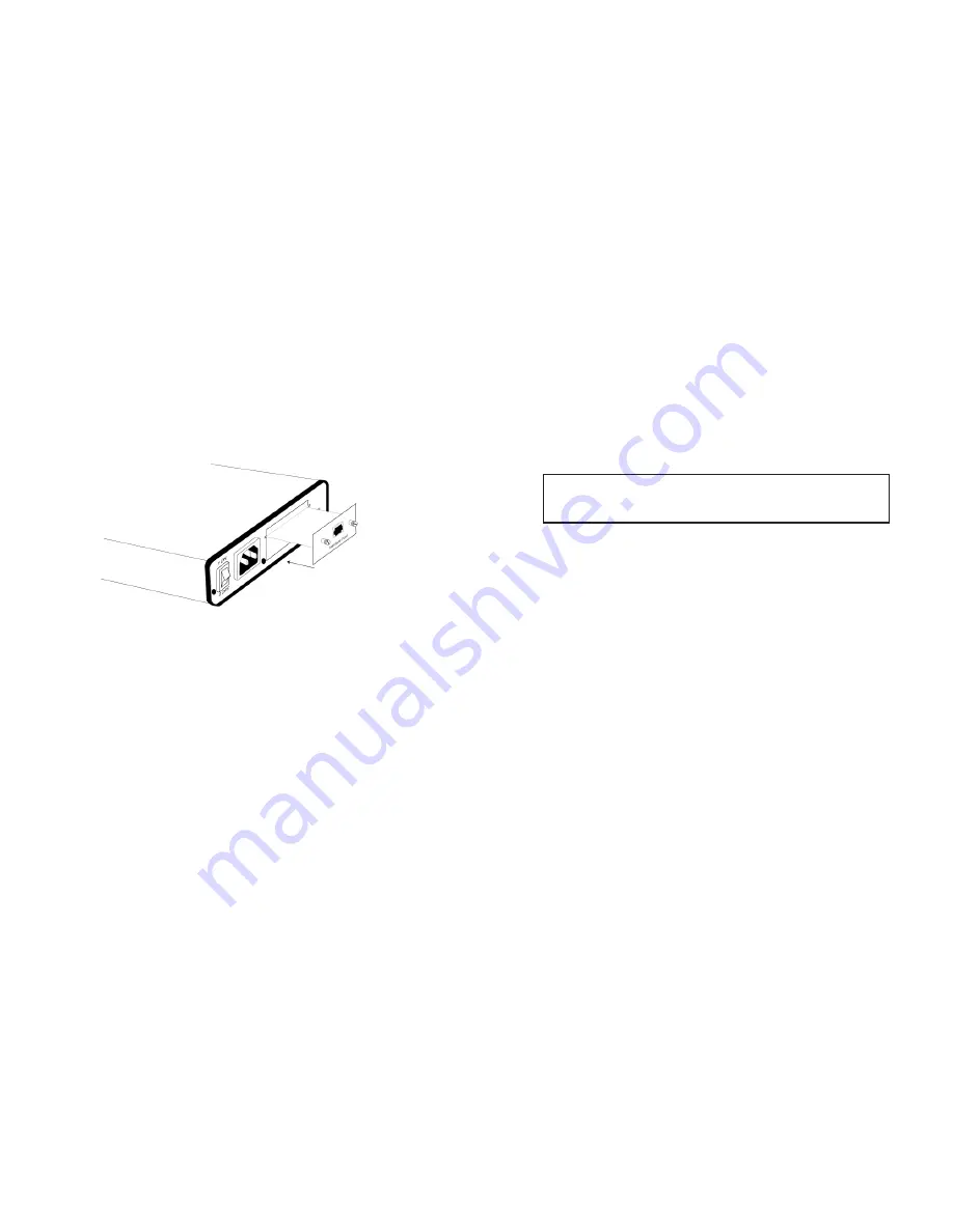
other.  The drawing below shows how a 

QuikConnect™ Module plugs

into the back of the Model 2073.  Figure 4 below shows how a
QuickConnect

TM

Module plugs into the back of the Model 2073.

4.2.1   Changing 

QuikConnect™ Modules

When you purchase a particular version of the Model 2073, it

should be shipped to you with the appropriate 

QuikConnect™ Module

already installed.  If you need to install a different 

QuikConnect™

Module, follow these steps:

Removing the Existing 

QuikConnect™ Module 

1)  Turn the power switch off.  Leave the power cord plugged into

a grounded outlet to keep the unit grounded.

2)  Loosen the two thumbscrews on the module by turning them

counterclockwise.

3)  Grasp the two thumbscrews and gently pull the module from

the unit.  Apply equal force to the thumbscrews to keep the
module straight during the removal process

Installing the New 

QuikConnect™ Module 

1)  Make sure the power switch is off.  Leave the power cord

plugged into a grounded outlet to keep the unit grounded.

2)  Hold the module with the faceplate toward you and align the

module with the guide slots in the rear panel of the Model
2073.  

3) While keeping the module’s faceplate parallel with the Model

2073 rear panel, slide the module straight in – so that the card
edge contacts line up with the socket inside the chassis.     

4) With the card edge contacts aligned with the socket, firmly seat

the module by using your thumbs to apply pressure directly to
the right and left edges of the module faceplate.  Applying
moderate and 

even pressure should be sufficient to seat the

module.  You should hear it “click” into place.

5) To secure the module in place, push the thumbscrews into the

chassis and turn the screws clockwise to tighten.

4.2.2   Connecting to a “DTE” Device 

The serial port on most 

QuikConnect™ interface modules (all

except the X.21 module) is hard-wired as a DCE.  Therefore these
modules “want” to plug into a DTE such as a terminal, PC or host.
When making the connection to your DTE device, use a straight
through 
cable of the shortest possible length—we recommend 6 feet
or less.  When purchasing or constructing an interface cable, please
refer to the pin diagrams in Appendix C as a guide. 

4.2.3   Connecting to a “DCE” Device

If the Model 2073’s QuikConnect™ interface module is hard-wired

as a DCE (all except the X.21 module), you must use a 

null modem

cable when connecting to a modem, multiplexer or other DCE device.
This cable should be of the shortest possible length—we recommend 6
feet or less.  When purchasing or constructing a null modem interface
cable, use the pin diagrams in Appendix C as a guide.  

12

NOTE:

The card edge connector should meet the socket when

it is almost all the way into the chassis.  If you encounter a lot of
resistance, remove the module and repeat steps 2 & 3.

FIgure 5. Installation of Model 2073 Plug-in Serial Interface Module

Summary of Contents for Kilo-Link 2073

Page 1: ... MODEL 2073 Kilo Link 64k G 703 Access Converter Rate Adapter Part 07M2073 A Doc 0311091UA Revised 12 4 99 SALES OFFICE 301 975 1000 TECHNICAL SUPPORT 301 975 1007 http www patton com An ISO 9001 Certified Company ...

Page 2: ...any damages incurred by the use of this product These damages include but are not limited to the following lost profits lost savings and incidental or consequen tial damages arising from the use of or inability to use this product Patton Electronics specifically disclaims all other warranties expressed or implied and the installation or use of this product shall be deemed an acceptance of these te...

Page 3: ...d Synchronization Internal external or network clocking options Test Mode controlled by switch or by local DTE V 24 and V 35 Versions Only Complies with CCITT ITU G 823 Jitter Control Specifications Built in surge protection and transformer isolation Point to Point distance up to 5250 ft 1600m on 24 AWG twisted pair 120 ohm twisted pair network termination 2 2 DESCRIPTION The Patton Model 2073 sta...

Page 4: ...Rates The DTE synchronous and asynchronous data are determined by the combined switch settings of S1 1 S1 2 S1 3 and S1 4 The follow ing table lists all the possible switch combinations and the correspon ding DTE data rates NOTE1 The four data rate configuraton switches are ignored when Octet Timing Mode is selected S2 1 is set to the On position D8 1 In Octet Timing Mode the data rate defaults to...

Page 5: ...ous and Synchronous DTE applications External transmit clock source is not a valid setting for asynchronous applications Switch S1 8 Local V 54 Preparatory Phase Reception Enable Disable Use switch S1 8 to control the reception of the V 54 remote digital loopback preparatory phase bit pattern by the local Model 2073 When this switch is On the local 2073 will respond to any V 54 loopback requests t...

Page 6: ...t the RJ 45 port of the Model 2073 to the RJ 45 jack provided by your digital service carrier using a straight through twisted pair cable between 19 and 26 AWG The signal pin relationships are shown in Figure 4 below Figure 4 64K G 703 Interface 4 2 Connection Over Private Twisted Pair If you wish to connect the Model 2073 to another Model 2073 or compatible G 703 device over private twisted pair ...

Page 7: ...odule straight in so that the card edge contacts line up with the socket inside the chassis 4 With the card edge contacts aligned with the socket firmly seat the module by using your thumbs to apply pressure directly to the right and left edges of the module faceplate Applying moderate and even pressure should be sufficient to seat the module You should hear it click into place 5 To secure the mod...

Page 8: ... domestic and international power cords DC Power Supply option Model 2073 DC operates in 48 VDC environments and is equipped with a 3 pin terminal strip style con nector 4 3 1 Connecting to an AC Power Source The Universal Interface AC Supply is equipped with a male IEC 320 power connection A domestic US power supply cord is sup plied with the unit at no extra charge To connect the standard or uni...

Page 9: ...s once to indicate that a CRC error has occurred during normal operation or bit errors have occurred during 511 511E tests 15 TM glows yellow to indicate that the Model 2073 has been placed in Test Mode The unit can be placed in test mode by the local user or by the remote user SYNC Glows green to indicate a valid G 703 connection 5 3 TEST MODES The Model 2073 offers two V 54 loop diagnostics Loca...

Page 10: ...al polynomial The receiving Model 2073 then decodes the received bits using the same polynomi al If the received bits match the agreed upon pseudo random pattern then the 2073 s and the communication link s are functioning proper ly 17 511 Initiates a built in 511 bit pseudo random pattern generator and detector 511 with Errors Initiates a built in 511 bit pseudo random pattern generator and detec...

Page 11: ...260 VAC via IEC 320 shrouded male connector 48 VDC option 10 watts Temperature Range 32 122 F 0 50 C Altitude 0 15 000 feet Humidity up to 90 non condensing Dimensions 7 3 x 6 6 x 1 62 185mm x 168mm x 41mm Weight 2 02 lbs 92 kg 19 A AP PP PE EN ND DI IX X B B PATTON ELECTRONICS MODEL 2073 FACTORY REPLACEMENT PARTS AND ACCESSORIES Patton Electronics Model Description IM1 A V 24 with DB25F IM1 B RS4...

Page 12: ...Loop 19 RTS Request to Send 20 DTR Data Terminal Ready 21 DL Remote Digital Loop 22 DSR Data Set Ready 23 DTR Data Terminal Ready 24 XTC External Transmit Clock 25 TM Test Mode A AP PP PE EN ND DI IX X C C PATTON ELECTRONICS MODEL 2073 INTERFACE PIN ASSIGNMENT Continued V 35 Interface M 34F Female Connector DCE Configuration Pin Signal B SGND Signal Ground C RTS Request to Send D CTS Clear to Send...

Page 13: ...e Connector DTE DCE Configuration Pin Signal 1 Frame Ground 2 T Transmit Data A 3 C Control A 4 R Receive Data A 5 I Indication A 6 S Signal Element Timing A 7 BT Byte Timing A 8 SGND Signal Ground 9 T Transmit Data B 10 C Control B 11 R Receive Data B 12 I Indication B 13 S Signal Element Timing B 14 BT Byte Timing B 23 ...

Reviews: