background image

4

2.3  TYPICAL APPLICATION

The Model IM1/I QuickConnect™ is designed to plug directly into

the rear of a Patton Electronics baseband modem (i.e. Model 1090 or
1092).   The Model IM1/I is designed to be used as one of a pair of
units.  Figure 1 (below) illustrates a typical Model IM1/I installation.

Corporate Headquarters

LAN

LAN

Remote/Satellite Office

Ethernet WAN Bridge

QuikConnect™ Module

Ethernet WAN Bridge

QuikConnect™ Module

DDS Network 

(Model 2530)

PCM Network (Model 

2073)

768k Leased Line 

(Model 1094)

512k Leased Line 

(Model 1093)

128k Leased Line 

(Model 1092)

64k Leased Line 

(Model 1090)

128k Single Fiber 

(Model 1184)

256k Single Fiber

(Model 1185)

Figure 1.

Typical Model IM1/I application

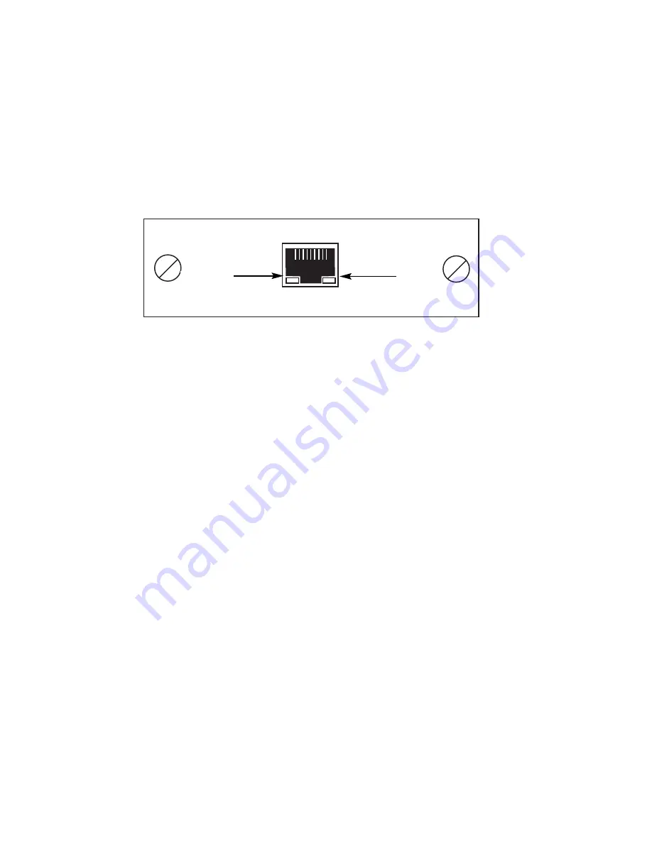
6.3  LED STATUS MONITORS

The Model IM1/I features two LEDs that monitor  general operating

status and the 10Base-T twisted pair link integrity.  Figure 6 (below)
shows the LEDs located directly beneath the RJ-45 jack.  Following
Figure 6  is a description of each LEDs function.

Status

Blinks yellow from one to eleven times to indicate 
system status.  Each pulse pattern is separated by a 
2 second “off” period.  Greater pulse patterns have 
higher priority (buffer saturation has greater priority 
than an empty MAC table). Valid system statuses 
are:

1 pulse  = system status is okay
2 pulses = no MAC entries in the MAC Address Table
3 pulses = Clear to Send (CTS) or Carrier Detect 

(DCD) from base unit are not asserted

4 pulses = IM1/I buffer is saturated
5 pulses = WAN receive frame(s) too large
6 pulses = WAN receive frame(s) not octet aligned
7 pulses = WAN receive frame(s) aborted
8 pulses = Detected WAN receive frame(s) with CRC
9 pulses = Detected LAN receive frame(s) too large
10 pulses = Detected LAN receive frame(s) not octet 

aligned

11 pulses = Detected LAN receive frame(s) with bad 

CRC

Link

Glows green to indicate good link integrity on the 
10Base-T twisted pair line.

Quik-Connect

 Interface Module

Interface Port

Figure 6.

Model IM1/I Panel

Status LED

Link LED

Summary of Contents for IM 1/I

Page 1: ...MODEL IM 1 I Ethernet Bridge Module SALES OFFICE 301 975 1000 TECHNICAL SUPPORT 301 975 1007 http www patton com Part 07MIM1 I E Doc 090101U Rev F Revised 1 22 08 C E R T I F I E D An ISO 9001 Certif...

Page 2: ...with the limits for a Class A computing device in accordance with the specification in Subpart J of Part 15 of FCC rules that are designed to provide reasonable protection from such interference in a...

Page 3: ......

Page 4: ...d RAM Modular 10Base T connection RJ 45 Two LED indicators status link integrity 2 2 DESCRIPTION The Patton IM1 I QuikConnect Ethernet WAN bridge module installs in Patton s copper and fiber base unit...

Page 5: ......

Page 6: ...figured for these communications until explicit LCP or NCP packets close the link down or until some external event occurs The PPP Bridging Control Protocol BCP defined in RFC 1638 configures and enab...

Page 7: ......

Page 8: ...g of your base unit corresponds to the throughput of your IM1 I bridge module Use higher speeds to allow maximum throughput to your extended LAN NOTE The IM1 I only supports synchronous speeds 2 Clock...

Page 9: ......

Page 10: ...ct Module plugs into the rear of the base unit NOTE The card edge connector should meet the socket when it is almost all the way into the chassis If you encounter a lot of resistance remove the module...

Page 11: ......

Page 12: ...n the base unit user manual Please refer to the base unit manual for connection details WARNING The Model IM1 I interface card has been specifically designed to work with UI and DC versions of Patton...

Page 13: ......

Page 14: ...tem statuses are 1 pulse system status is okay 2 pulses no MAC entries in the MAC Address Table 3 pulses Clear to Send CTS or Carrier Detect DCD from base unit are not asserted 4 pulses IM1 I buffer i...

Page 15: ......

Page 16: ...45 Female Connector DTE Configuration Pin Signal 1 TD data output from IM1 I 2 TD data output from IM1 I 3 RD data input to IM1 I 4 no connection 5 no connection 6 RD data input to IM1 I 7 no connect...

Page 17: ......

Page 18: ......

Page 19: ......

Page 20: ......

Reviews: