


8
9
5.0 INSTALLATION
The Model IM1/I is completely plug and play. This section tells you
how to make the connections.
5.1 INSTALLING THE QUICKCONNECT™ MODULE
Each Quick Connect Module™ has a 50-pin card edge connector
on one side and an ethernet interface on the other. The instructions
below describe how to remove the existing QuickConnect™ Module
and how to install the new IM1/I module. If your base unit does not
have an existing QuickConnect™ already installed, please skip to
section 3.2.2.
5.1.1 Removing the Existing QuickConnect™ Module
1) Turn the power switch off. Leave the power cord plugged into a
grounded outlet to keep the unit grounded.
2) Loosen the two thumbscrews on the module by turning them
counterclockwise.
3) Grasp the two thumbscrews and gently pull the module from the
unit. Apply equal force to the thumbscrews to keep the module
straight during the removal process
5.1.2 Installing the New QuickConnect™ Module
1) Make sure the power switch on the base unit is off. Leave the
power cord plugged into a grounded outlet to keep the unit
grounded.
2) Hold the module with the faceplate toward you and align the
module with the guide slots in the rear panel of the base unit.
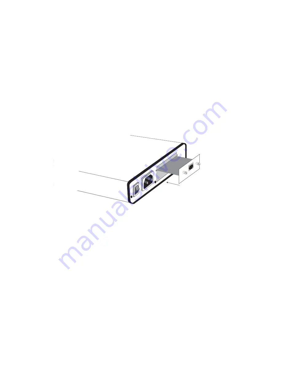
3) While keeping the module’s faceplate parallel with the base unit
rear panel, slide the module straight in–so that the card edge
contacts line up with the socket inside the chassis. Figure 4
(below) shows how a Quick Connect Module plugs into the rear
of the base unit.
NOTE:
The card edge connector should meet the socket when
it is almost all the way into the chassis. If you encounter a lot of
resistance, remove the module and repeat steps 2 & 3.
4) With the card edge contacts aligned with the socket, firmly seat
the module by using your thumbs to apply pressure directly to
the right and left edges of the module faceplate. Applying
moderate and
even
pressure should be sufficient to seat the
module. You should hear it “click” into place.
5) To secure the module in place, push the thumbscrews into the
chassis and turn the screws clockwise to tighten.
0 OFF
1 O
N
Line
Int
er
face
P
or
t
Figure 4. Installation of Model IM 1/I Plug-in Serial Interface Module


