


35
36
4.0 INSTALLATION
This section describes the functions of the Model 1001R14 rack
chassis, tells how to install front and rear Model 2710RC Series cards
into the chassis, and how to connect to the twisted pair interface and
the serial interface.
4.1 THE MODEL 1001R14 RACK CHASSIS
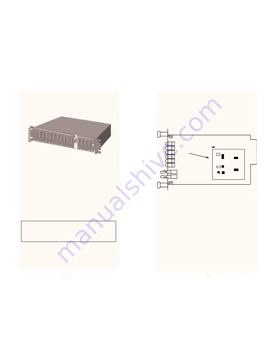
The Model 1001R14 Rack Chassis (Figure 9, below) has fourteen
or sixteen device card slots, plus a single power supply or dual redun-
dant power supplies. Measuring only 3.5” high, the Model 1001R14 is
designed to occupy only 2U in a 19” rack. Sturdy front handles allow
the Model 1001R14 to be extracted and transported conveniently.
4.1.1 The Rack Power Supply
The power supply included in the Model 1001R14 rack uses the
same mid-plane architecture as the modem cards. The front card of
the power supply slides in from the front, and the rear card slides in
from the rear. They plug into one another in the middle of the rack.
The front card is then secured by thumb screws and the rear card by
conventional metal screws.
Powering up Your 1001R14 Rack
The power supplies that come with your 1001R14 rack system are
equipped with a power entry connector on the rear power supply card.
The power supplies are
Hot-Swappable, so you are not required to
remove the cards from the rack while applying power to the system.
NOTE: Please refer to the Model 1001R14 Series User Manual
AC and DC Rack Mount Power Supplies for fuse and power card
replacement information.
4.2 INSTALLING THE INTERFACE DRIVER BOARD
The DTE electrical interface on the 2710RC is determined by a
DTE daughter board that is mounted on the main board by a 20 pin
jumper. Figure 10 shows the Interface Driver Board on the top of the
2710RC main board.
Follow the instructions below to install or change the correct inter-
face for your application.
1.
With the 2710RC front card pulled out of the rack chassis,
locate the driver board on top of the 2710RC front card.
2.
Lift the interface drive board gently off the main pc board.
3.
Locate the correct interface on the bottom of the driver board.
For example, the RS-232/V.35 interface board is marked
“THIS SIDE UP FOR V.35” on one side and “THIS SIDE UP
FOR RS-232” on the other side. Other “single interface”
boards (e.g. RS-530) are marked with the with “FRONT” on
one side of the board.
4.
Re-orient the interface board into the socket with the appropri-
ate interface pointed UP and with the arrow pointing toward
the front panel of the Model 2710RC pc board.
Figure 10. Interface Driver Board
FRONT RS-530
Interface Driver
Board
Figure 9. Model 1001R14 Rack Chassis with power supply
NOTE: If the ERR LED on the front of your unit is flashing (or on) you
may have clocking problems causing Fifo Slips. By pressing ‘h’ you
will refresh the unit information screen. If the Fifo Slip number incre-
ments, this signifies a clock problem. Review your settings for Clock
Mode, Tx Data Clock, and Tx Clock Invert to solve the problem.


