


3.2 CONFIGURATION SWITCHES SW1 - SW8
This section provides detailed information about the function of
each DIP switch and lists all possible settings.
Switch 1: Hardware/Software Control/BERT Direction
The setting for Switch 1 determines whether the 2036P uses hard-
ware or software (i.e. XON/XOFF) flow control. Switch 1 is alternative-
ly used to determine the direction of the BERT output message when-
ever the BERT is activated (See Switch 2, below).
Switch 2: Bit Error Rate Test (BERT)
Use Switch 2 to activate a Bit Error Rate Test (BERT) in the direc-
tion of the serial
or parallel interface. This test can be used to deter-
mine whether the 2036P is working properly. When BERT is activated,
the 2036P outputs the following Barber Pole pattern, which represents
every ASCII character on a standard US keyboard:
0123456789:;<=>?@ABCDEFGHIJKLMNOPQRSTUVWXYZ[\}^_’abcdefghijklmnopqrstuvwxyz{|}~
NOTE: When you activate the BER Test, the 2036P “memorizes” the setting of
Switches S1, S3,S4, S5, S6, S7, and S8 to perform the test. If you modify any of
these switches, you must de-activate Switch 2 in order for the changes to take effect.
5
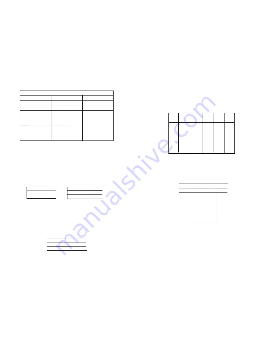
DIP SWITCH SUMMARY TABLE
Position
Function
Factory Default
SW1
Flow Control
Off
SW2
Bit Error Rate Test
Off
De-Activated
SW3
Data, Parity, Stop Bits
Off
SW4
Data, Parity, Stop Bits
Off
SW5
Data, Parity, Stop Bits
Off
SW6
Data Rate
Off
SW7
Data Rate
Off
SW8
Data Rate
Off
Hardware
8B, NP, 1S
38400 bps
}
}
Flow Control SW1
Hardware
OFF
Software
ON
BERT Direction SW1
Parallel
OFF
Serial
ON
Bit Error Rate
SW2
BERT Activated
ON
BERT De-activated
OFF
Switch 3 through 5: Data, Parity and Stop Bit
Switches 3 through 5 are used to specify the data, parity and stop
bits. The following table shows the settings that may be used:
Switches 6 through 8: Frequency and Data Rate
Switches 6 through 8 determine the frequency and data rate. The
following chart shows the settings that may be used:
6
1200
OFF
OFF
ON
2400
ON
OFF
ON
4800
ON ON
OFF
9600
OFF
ON
ON
19200
ON
ON
ON
38400
OFF
OFF
OFF
57600
ON
OFF
OFF
115200
OFF
ON
OFF
Serial Data Rate
Data Rate
SW6
SW7
SW8
7B
EP
1S
ON
ON
ON
7B
OP
1S
OFF
ON
ON
7B
NP
2S
ON
OFF
ON
7B
EP
2S
OFF
OFF
ON
7B
OP
2S
ON
ON
OFF
8B
EP
1S
OFF
ON
OFF
8B
OP
1S
ON
OFF
OFF
8B
NP
1S
OFF
OFF
OFF
Stop
Data
Parity
Bit
SW3
SW4
SW5


