background image

11

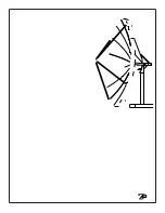
Overlap

Reflector Assembly

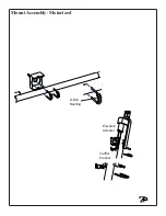
1.  Install the Radial Beams to the Hub Angles which are pre-installed to the hub, using hard-
ware  labeled- 

Radial Beam to Hub

.  Use 3 bolts, 6 washers, and 3 nuts per.  Tighten this

hardware as it is installed.
NOTE:  Be sure to place the Radial Beam on the outside of the Hub angle as shown.

2.  Now install all of the Outboard Skirts on the end of the Radial Beams (bent edge down) using

hardware labeled Outboard Skirt

.   Leave this hardware loose.

NOTE:  One end has a formed “overlap”.  Place this end on the outside.

Radial Beam
to outside of
Hub Angle

1.  Install 

4M38004 (ANGLE, 3.8 HUB) to hub as pictured below 

    Make sure the cut corner is towards the BOTTOM of the hub assembly. 
2. Once all 4M38004 (ANGLE, 3.8 HUB) are attached fasten hub to King post assembly as pictured on   
    page 7.
3. Once hub is attached to King post assembly begin to attach 238006 (RADIAL BEAM  3.8 PRIME)
    to  4M38004 (ANGLE, 3.8 HUB).
    Make sure that Radial Beams are to the Out side of the hub angle and pictured below.      
4. With all Radial Beams in place and hardware in place install all of the 238005 (OUT BRD SKIRT, 3.8                
    PRIME) on the end of the Radial Beams (bent edge down) Make sure overlap is in proper place as 
    pictured below.  Leave this hardware loose at this time.

Summary of Contents for Patriot 3.8m Commercial Antenna King Post Mount

Page 1: ...3 8m Commercial Antenna King Post Mount...

Page 2: ...ance with any part of this claim procedure may invalidate this warranty in whole or in part THIS WARRANTY IS EXPRESSLY IN LIEU OF ALL OTHER AGREEMENTS AND WARRANTIES ANY IMPLIED WARRANTY OF MERCHANTAB...

Page 3: ...Be prepared to safely handle these forces at unexpected moments Do not at tempt to assemble move or mount dish on windy days or serious even fatal accidents may occur PA TRIOT ANTENNA SYSTEMS is not...

Page 4: ...obstructions etc When selecting look angle be sure to observe and take readings approximately 10 deg to the left and right above and below your selected look angle Before Ground Pole Installation the...

Page 5: ...5...

Page 6: ...rances D C B A A B C D 1 2 3 4 5 6 7 8 8 7 6 5 4 PROPRIETARY AND CONFIDENTIAL PATRIOT ANTENNA SYSTEMS IS PROHIBITED WITHOUT THE WRITTEN PERMISSION OF 001 10 20 2006 DRAWING IS THE SOLE PROPERTY OF PAT...

Page 7: ...6 8SCHEDULE 80 L 120 2 CONCRETE 3000psi AT 28 DAYS POURED AGAINST UNDISTURBED SOIL ALLOW CONCRETE 24 HOUR SET TIME 3 ESTIMATED AMOUNT OF CONCRETE NEEDED 62 CUBIC FOOT 4 SOIL BEARING CAPACITY 2000psf...

Page 8: ...coverage of 132 degrees The pad bolts must be placed in the concrete to allow coverage of the desired portion of the satellite arc Please consult a satellite chart software program or a qualified con...

Page 9: ...in post clevis double nutting it with the pre as sembled washers and nuts Attach the thru hole end to the A frame attachment details Snug the Lock down bar hardware so the Hub assembly can be safely p...

Page 10: ...can be safely placed 3 With 2 helpers place the hub assembly in the zenith bird bath position on top of the King Post A frame as shown using the preassembled hardware in place on the A frame Note the...

Page 11: ...e outside Radial Beam to outside of Hub Angle 1 Install 4M38004 ANGLE 3 8 HUB to hub as pictured below Make sure the cut corner is towards the BOTTOM of the hub assembly 2 Once all 4M38004 ANGLE 3 8 H...

Page 12: ...hole Pull the tapered alignment tools and install that hardware Leave hardware loose at this time Continue installing the remaining Petals using this method Tightening Procedure Important 6 Starting a...

Page 13: ...13...

Page 14: ...w complete Now lower the antenna out of the bird bath position To adjust the antenna toward the selected satellite you must first know its elevation angle above horizon This will be the reference angl...

Page 15: ...il maximum transponder signal is achieved External Toothed Washer Grounding Grounding Antenna Feed Cables 1 Ground antenna feed cables in accordance with current National Electric code and local elec...

Page 16: ...13 Operational Wind 50mph Survival Wind 125mph Operational Temp 40 to 140 F Rain Operational 1 2in hr Survival 3in hr Ice 1 in Radial or 1 2 in 60mph wind Weight Reflector 590 lbs Mount 680 lbs Gain 4...

Reviews: