background image

Appendix 3: Ring Protection 

Ethernet wiring schemes are based on a ‘star’-wiring topology. Ring (or loop) data wiring – 
where the last device in a chain is wired back to the first device – is forbidden.  Only one data 
path between any two devices is allowed.   

But star-wiring layouts  are prone to single point failures. Unlike DMX512 transmission, 
passive data ‘thru’ connections are not possible with Ethernet, which means there is no 
redundancy under normal operation. A severed cable or power loss to a switch can mean 
the loss of some or even all show control. 

Ring Protection allows the deliberate –  and designed –  use of a ring wiring system for 
Ethernet communications. When in this mode, VIA  switches ignore data traffic on one 
segment of the ring, while monitoring the integrity of the remaining connections. If an 
interruption is detected, the unused ring segment is activated and full communication is 
restored. Fail-over time is between 50 and 75 milliseconds, or two to four DMX packets. 

Requirements and Limitations 

VLANs must be enabled to use Ring Protection. The mode uses a dedicated VLAN to monitor 
the integrity of the ring, called a Control VLAN. All switches must use the same Control 
VLAN. By default, VLAN 4095 is used. This does not mean your VLAN range needs to extend 
to 4095. Typically an entertainment network may use 1-3 or 1-10 VLANs. 

Only ports 15 thru 18 may be used with this feature. 

Ring Protection works with Pathway VIA switches only. Switches from other manufacturers 
can co-exist on the network, but should not be placed in-line with the ring. 

Definitions 

Master  switch monitors the integrity of communications. Only one switch on the network 
may be configured as the master. If choice is available, the least busy switch, with the most 
reliable power source, preferably on an uninterruptible power supply, should be chosen as 
the master. 

Transit switches receive and forward the ring monitoring packets. All switches other than the 
Master must be set as transit switches. 

Note:  Ring Protection wiring topology is not structured. No care need be taken when 
connecting primary and secondary ports together – any arrangement is acceptable. 


Summary of Contents for 6716

Page 1: ...6716 VIA16 PoE Ethernet Switch User Guide and Manual 5 25 2018 Acuity Brands Lighting Canada 1439 17 Ave SE Calgary AB T2G 1J9 Phone 1 403 243 8110 www pathwayconnect com...

Page 2: ...ity of Service QoS 15 Factory Default 16 Port Properties and Configuration 17 VLAN Type 20 VLAN ID 21 Art Net Trap and Convert 22 Port Enable Disable 22 Port PoE Setup Status 23 LLDP Link Partner 23 P...

Page 3: ...ontrol over the data path The VIA16 is easily configured and upgraded using the freely available software tool Pathscape Installation Instructions The VIA16 switch is DIN mountable and intended for us...

Page 4: ...the external power supply must provide 48 50 VDC with enough watts to satisfy the draw of connected equipment Class 3 PoE 15 4 W is available on the first 12 Ethernet ports If you intend on using Cla...

Page 5: ...operties and send transactions to devices refer to the Pathscape manual Network Setup From the factory the VIA16 s IP address is static and set to 10 X X X where X is between 0 and 254 with a subnet m...

Page 6: ...transaction Serial Number Factory assigned Pathway serial number IP Address Switch IP address IP Subnet Mask Switch subnet mask IP Default Gateway Switch default gateway Enable VLANs Enable or disable...

Page 7: ...apable of supplying PoE 48VDC Green PoE LED on VIA16 panel will also indicate this lit if present off if not present PoE External Supply Power W Enter the power rating of the external supply in Watts...

Page 8: ...n The creation of a map of the network showing which devices and which ports to associate with a given VLAN is strongly recommended prior to configuration EXTREMELY IMPORTANT NOTE When configuring one...

Page 9: ...he switch s management processor For efficient switch operation the VLAN range should be kept as small as necessary If the Management VLAN is accidentally set to a value outside the VLAN range it may...

Page 10: ...nt VLAN VLAN ID 1 by default is automatically assigned an IP and subnet mask All other VLANs default to a null IP address value 0 0 0 0 From the Network Settings for each VLAN assign a unique IP per s...

Page 11: ...server The DHCP server should be enabled prior to setting other connected devices to a Dynamic IP mode or being connected to the network VLAN In some cases it may be necessary to reboot connected devi...

Page 12: ...ach switch operating an IGMP Querier on a VLAN must have valid IP settings on that VLAN The IP settings may be static or dynamically established using the DHCP IMPORTANT Two IGMP queriers should be ac...

Page 13: ...tection should only be configured and enabled after all other VLAN configuration has been completed During the setup and configuration of the Ring Protection feature communication between devices may...

Page 14: ...up and then disabled after verifying there are no loops present For more information please refer to the Appendix Art Net Alternate Mapping This feature is used in conjunction with the Art Net Trap an...

Page 15: ...member that giving all data high priority is the same as treating all traffic equally Property Description Quality of Service Disabled default Disables QoS based routing All traffic is treated equally...

Page 16: ...cidentally set to a value outside the VLAN range it is possible to reset the switch to factory settings While powered insert the tip of a pen or paperclip into the small hole in the front panel next t...

Page 17: ...n in the subdevice port properties panel Some are editable while others are read only Property Description Name Name of the port Default is the port number User defined Notes Additional notes User def...

Page 18: ...affic per second Read only Tagged Uplink Untagged normal default Only data belonging to the port s specified VLAN ID will be transmitted Typically set when connected to end equipment Tagged Uplink All...

Page 19: ...W Class 3 Uses up to 15 4W PoE Active Draw mW Consumption as reported by the PoE controller in milliwatts PoE Power Allocation mW Reports the maximum draw in milliwatts allowed by the PoE class or the...

Page 20: ...or the lowest ID of the VLAN range Ports set as Untagged only transmit data packets in the VLAN specified by the ID and are typically connected to end equipment Ports set as Tagged do not require a V...

Page 21: ...e port In Pathscape s VLAN Configuration tab if you expand a VLAN and highlight one of the switches using that VLAN one of the Properties is the VLAN NAME This can be set to something appropriate like...

Page 22: ...converted to the analogous sACN universe Due to how Art Net universes are numbered there is the possibility of an off by one error Change the Art Net Alternate Mapping option should the universe mappi...

Page 23: ...b PoE is allocated on a first come first serve basis dependent on the order devices are plugged into the switch Troubleshooting tip If the green PoE LED on the front panel is blinking the maximum allo...

Page 24: ...e port may also be disabled NOTE It is not possible to force a device to connect at a speed faster than the device s network interface hardware will support For fiber ports the Link Mode has only two...

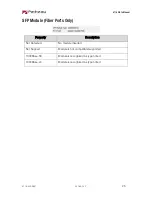
Page 25: ...18 05 25 25 SFP Module Fiber Ports Only Property Description Not Detected No module inserted Not Support Module is not compatible supported 1000Base SX Module is recognized as type noted 1000Base LX M...

Page 26: ...s is configured correctly and is on the same subnet and IP range as the computer Open Pathscape and select the device in the Device list Right click the device and choose Firmware This will bring up t...

Page 27: ...type of fiber installed either Single Mode or Multi Mode 5 The SFP must support the distance required which in turn determines the optical wavelength 850nm is typically used for runs up to 550m while...

Page 28: ...plink and Tagged Normal Untagged ports belong to a specific VLAN as configured by the user and will only pass traffic that belongs to that VLAN Typically connected to end equipment Uplink Tagged ports...

Page 29: ...VIA switches will typically be set as Uplink Tagged so multiple VLANs may be forwarded between switches or when a VLAN must be forwarded through an intermediate switch where that VLAN is not in use on...

Page 30: ...VLAN ID 1 2 3 4 5 6 7 8 Label IP Address Subnet Mask Default Gateway IGMP Snooping IGMP Querier DHCP Server Art Net Alternate Mapping QoS Level...

Page 31: ...6716 VIA16 Manual 6716 200 REV1 2018 05 25 31 Switch Label Port 1 2 3 4 5 6 7 8 9 10 11 12 13 14 15 16 17 18 Connected Device Normal Uplink VLAN ID ArtNet to sACN PoE Max Link Mode SFP Type...

Page 32: ...packets Requirements and Limitations VLANs must be enabled to use Ring Protection The mode uses a dedicated VLAN to monitor the integrity of the ring called a Control VLAN All switches must use the s...

Page 33: ...er switch to break the ring topology All transit switches also must have one port configured as the secondary port The secondary port is actively used on transit switches Only ports 15 through 18 are...

Page 34: ...QoS settings used by VIA switches is shown in the following table QoS Setting Description Disabled default Disables QoS based routing All traffic is treated equally QoS Standard Queue 1 DSCP values 1...

Reviews: