background image

Troubleshooting

Second Edition 03/18/1997 – CSH  (con:K2AA V1.0)  031-300-190014_A.doc

17

Operating Errors

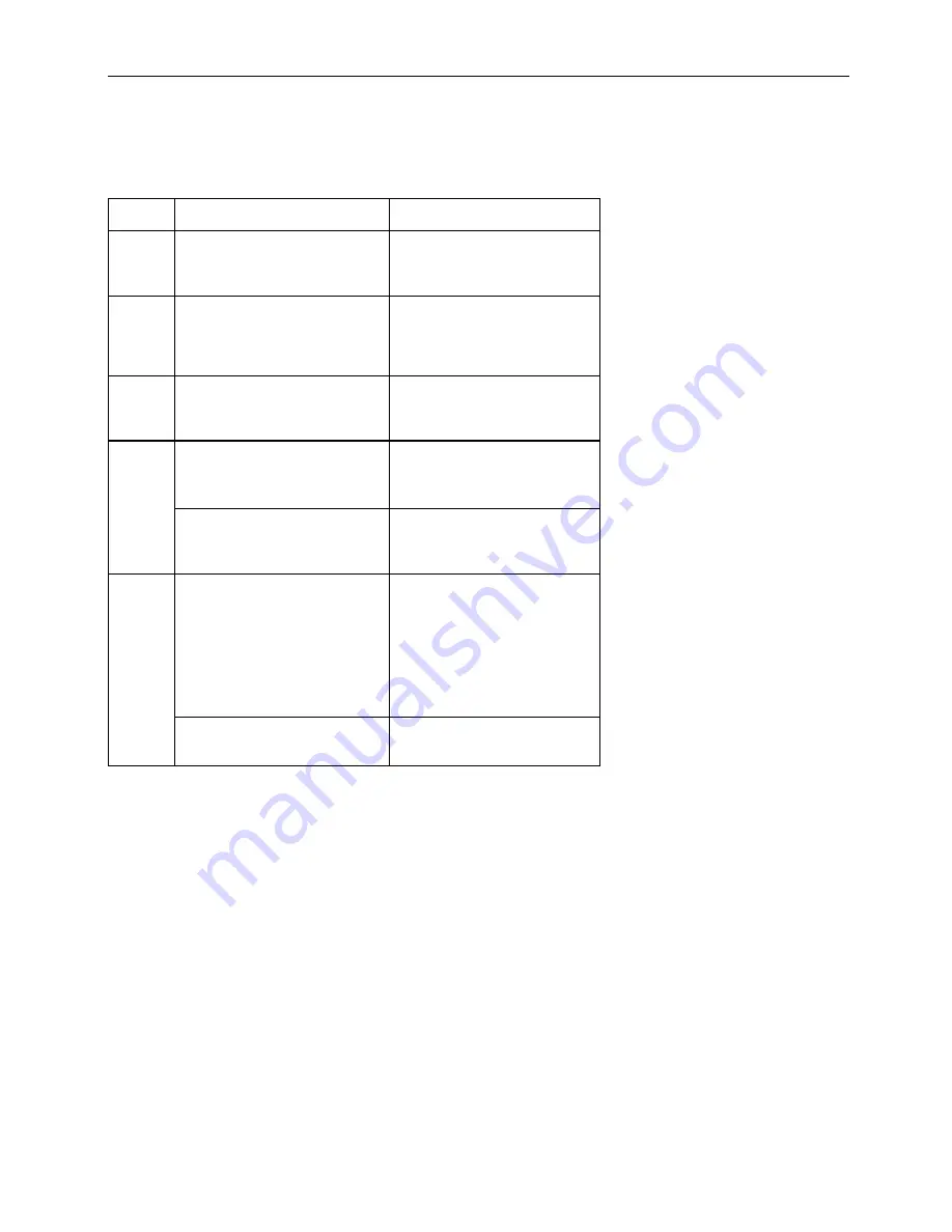
Malfunctions in the system that are caused by range exceeding or operating errors by the crane operator
himself are indicated on the display. These error codes are E01, E02, E03, E04, and the crane operator
himself can normally eliminate E05 and them.

Error

Code

Cause

Elimination

E01

Fallen below the minimum
radius or above the angle given
in the load capacity chart due to
luffing up the boom too far.

Luff down boom to a radius or
angle given in the load capacity
chart.

E02

The maximum radius or
minimum angle given in the load
capacity chart was exceeded
due to luffing down the boom
too far.

Luff up boom to a radius or
angle given in the load capacity
chart.

E03

Boom position is out of the
permissible working area (over
front).

Move boom back to the
permissible working area. See
lifting diagram in the load
capacity charts.

E04

Operating mode at the console
incorrectly set.

Correctly set operating mode to
the code assigned to the
operating mode of the crane.

Operating mode is not
permissible with the actual
crane configuration or boom
position

Be sure crane is set up
according to proper operating
configurations.

E05

Boom was telescoped too far or
not far enough, you may only
operate up to a certain
maximum or minimum boom
length or with load curves for
boom extension where you have
to telescope the main boom to a
certain length.

Telescope boom to correct
length, given in the load
capacity chart.

Length sensor adjustment
changed i.e. length sensor cable
slid off the length sensor drum.

For elimination, refer to service
manual.

Summary of Contents for DS 50

Page 1: ...Second Edition 03 18 1997 CSH con K2AA V1 0 031 300 190014_A doc LOAD MOMENT INDICATOR DS 50 0002 OPERATOR S MANUAL MANITEX...

Page 2: ......

Page 3: ...warranties of marketability and fitness for a particular purpose PAT shall not be liable for errors contained herein or for incidental or consequential damages in connection with the furnishing perfor...

Page 4: ......

Page 5: ...n 5 3 2 Control Identification 6 4 Pre Operational Inspection 9 4 1 Anti two block devices 9 4 2 Pre Operation Inspection and Calibration Verification 10 5 System Operation 12 5 1 Operating Mode Selec...

Page 6: ...nufacturer for specific crane operation and load limits 2 WARNINGS The LMI is an operational aid that warns a crane operator of approaching overload conditions and warns of overhoist conditions which...

Page 7: ...red in the central processor memory and evaluated in the microprocessor When limits are reached an overload warning signal is generated at the operator s console The fixed data regarding the crane suc...

Page 8: ...Operator s Manual DS 50 0002 4 Fig 1 Components of the LMI system PAT DS 50...

Page 9: ...ith an automatic test of the LMI system of lamps and audible alarm During the test the LC display shows 8 88 8 8 First the operating mode is determined by input of the operating code number System awa...

Page 10: ...rols that are described as follows Fig 2 Operating Console 1 LC Display 2 Load Moment Limit Light 3 Load Moment Prewarning Light 4 Alarm Light Anti Two Block 5 Button UP 6 Button DOWN 7 Button and Con...

Page 11: ...s condition has been reached Load Moment Prewarning Light The yellow LOAD MOMENT PRE WARNING LIGHT 3 will light up when the load on the crane reaches the defined prewarning area thus indicating that a...

Page 12: ...fer to chapter 5 3 Button OK Key for acknowledgment of an error message The correct setting of the operation mode and the reeving is of utmost importance for the proper function of the system and the...

Page 13: ...The hoist line runs through the A2B weight With even parts of hoisting line the weight shall be attached to the dead end line With odd parts of hoisting line the weight shall be attached to the line...

Page 14: ...the red warning light 4 sounding the audible alarm locking out of the hoist up and telescope out functions and if the overload shutoff option is installed a lockout of the boom down function will occ...

Page 15: ...all controls of the LMI before operating the crane see Section 3 2 Lifting a load of known weight and comparing the load to the information displayed on the LMI see Section 5 2 shall check the proper...

Page 16: ...start function automatically after system start Manually at each modification of the crane configuration by pressing key The operating mode key and the cursor keys light up The operating mode selectio...

Page 17: ...nd the cursor keys light up The reeving selection is displayed XX present reeving select reeving use cursor keys and to modify the reeving confirm selection By pressing again key The cursor keys and t...

Page 18: ...eeving selection are active the LC display serves as data display Press keys and to select the values There are 9 display positions Display Position Y Displayed Value XXXX 0 error message 1 main boom...

Page 19: ...upted so that 2 seconds later approx the cutoff relay is de energized 6 SERVICE AND MAINTENANCE Daily maintenance of the load moment indicator consists of inspecting The electrical wiring connecting t...

Page 20: ...correct the fault Faults within the electronic microprocessor shall be repaired by factory trained service personnel When these faults occur the competent service organization shall be contacted Malfu...

Page 21: ...us or angle given in the load capacity chart E03 Boom position is out of the permissible working area over front Move boom back to the permissible working area See lifting diagram in the load capacity...

Reviews: