Page 4
X
90+4°
A
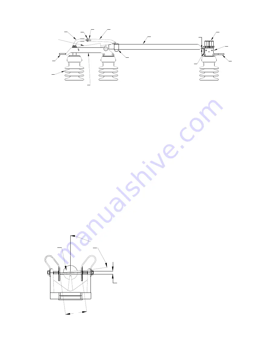
Fig. 4
End View Showing Blade Contact Angle
Blade Contact
End
Dimension D
A
B
Terminal
Pad
Rotating
Insulator
Blade
Fork Link
Blade Clamp
Tie Casting
Counterbalance
Terminal
Pad
Contact
Fingers
Jaw Casting
Blade Stop
Gooseneck Crank
Fig. 3 Typical Set of Current Carrying Parts
Important: If it is expected that the conductors to
be attached to the switch jaw will impose an
appreciable horizontal force, it is recommended
that the jaw insulator column be adjusted so that
the jaw fingers are slightly off center on the blade
contact, in a direction toward the hinge end.
Blade Contact Angle
—(Fig. 4) The allowable
difference in elevation from one side of the blade
contact to the other (dimension X) is 1/16” for
each 1” of contact width. Example: If contact
width (A) is 4 1/2”, then dimension (X) can be as
much as 9/32” and still be within the plus or minus
4 degree tolerance.
Also, Fig. 4 shows blade contact high on the right
and low on the left. The reverse is also acceptable,
high on the left and low on the right. It is common
to have both situations on one three-pole switch.
In fact, after all three poles have been adjusted in
the open position, and then closed, you may find
that one pole will be high on the right, one fairly
level and one high on the left. This is
due to many variables and tolerances plus the free
play or clearance in pin connections of all the
switches and control parts.
With the switch blade in the closed position, the
gooseneck crank arm and fork link will over-toggle
to the left of the switch center line when looking
from hinge to jaw end of the switch phase.
Note: switch blade angle in the blade clamp is set in
the factory. This is not an adjustment point for
blade contact angle.
Blade Height in Jaw
—In Fig. 3, dimension (D) can
vary from 0” to 5/8” with the switch in the closed
position. It is not usually possible to get this
dimension to be equal on all three poles of a three-
pole switch. If it’s necessary to adjust this
dimension, remove connecting pin (A) and turn
clevis (B) in or out ½ turn then reconnect and try
switch. Turning the clevis in will move the blade
away from the blade stop. Conversely, turning the
clevis out will move the blade closer to the blade
stop.
Note: clevis assembly is a left hand thread
connection!
Step 7—Mount Offset Bearing
For those installations requiring an offset bearing,
mount the offset bearing and its supporting base on
the structure in the position shown on the
installation drawing. Fig. 5 shows a typical
arrangement using the offset bearing. Check
operating crank for proper length radius and angle,
and stop crank for correct position. These are
defined in the notes on the installation drawing.


