012-02960D
2
!
Additional Equipment Needed:
*4. PASCO Microwave Transmitter
*5. PASCO Microwave Receiver
*6. 9 V Power Adapter
7. an oscilloscope, or an audio amplifier and
speaker, to monitor the output.
8. Banana plug connectors. (between the oscil
loscope and the modulation)
*
Items 4-6 are provided in the PASCO Microwave
Optics System (WA-9314B or WA-9316)
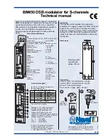
Operation
Set up the equipment as shown in the preceding
illustration. Turn on the microphone with the ON/OFF
switch found on the microphone battery compartment.
Point the Microwave Transmitter toward the Micro-
wave Receiver. Then:
•
To monitor the modulating signal, plug your os-
cilloscope into the banana plug connectors labeled
SCOPE on the Microwave Modulator. (see Fig-
ure)
•
To monitor the signal at the receiving end, plug
your oscilloscope or audio amplifier w/speaker
(not included) into the banana plug connectors
labeled OUTPUT on the top of the Microwave
Receiver. (see Figure)
•
If you wish to modulate the microwaves with the
triangular wave signal, unplug the microphone.
Adjust the frequency, amplitude, and bias of the
modulating signal using the controls on the Mi-
crowave Modulator. (The BIAS control adjusts
the DC voltage level of the Gunn Diode in the
Microwave Transmitter. The modulating signal
then varies the Gunn Diode voltage about this
DC voltage. Proper adjustment of the BIAS is
necessary to produce a linear, unclipped micro-
wave signal from the Gunn diode.)
Experiments
1. ADDING AN AUDIBLE OUTPUT TO MICRO-
WAVE EXPERIMENTS
The impact of most microwave experiments can be
improved by adding an audible output. The
maxima and minima of an interference pattern, for
example, seem somehow more real when they can
be heard in the variations in loudness of an audible
tone, instead of just seen as fluctuations in a meter
reading.
Any of the experiments in the manual that accom-
panied your PASCO Microwave Optics System can
be performed with an audible output. Just follow
the instructions listed above for using the triangular
wave output of the Modulator with an audio ampli-
fier and speaker.
2. MICROWAVE COMMUNICATIONS
With the simultaneous use of an oscilloscope and
an audio amplifier and speaker, this system is ex-
cellent for demonstrating microwave communica-
tions. The input signal can be the triangular wave
output of the modulator, or it can come from the
microphone or even a tape player.
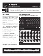
Typical View of Dual Trace Oscilloscope
Typical Equipment Settings
"#$%&'()
"*$+,&'()
-./0 1234 /567
89
%/2./-73
03:0.;.%.;<
=1>77$?7@?AB.03C
CH. 1 (Microwave Modulator)
CH. 2 (Receiver)
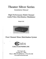
Modulator
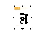
Receiver