


FFeatur
eatures
es
10
1
2
3
4 5
6
7
8
9
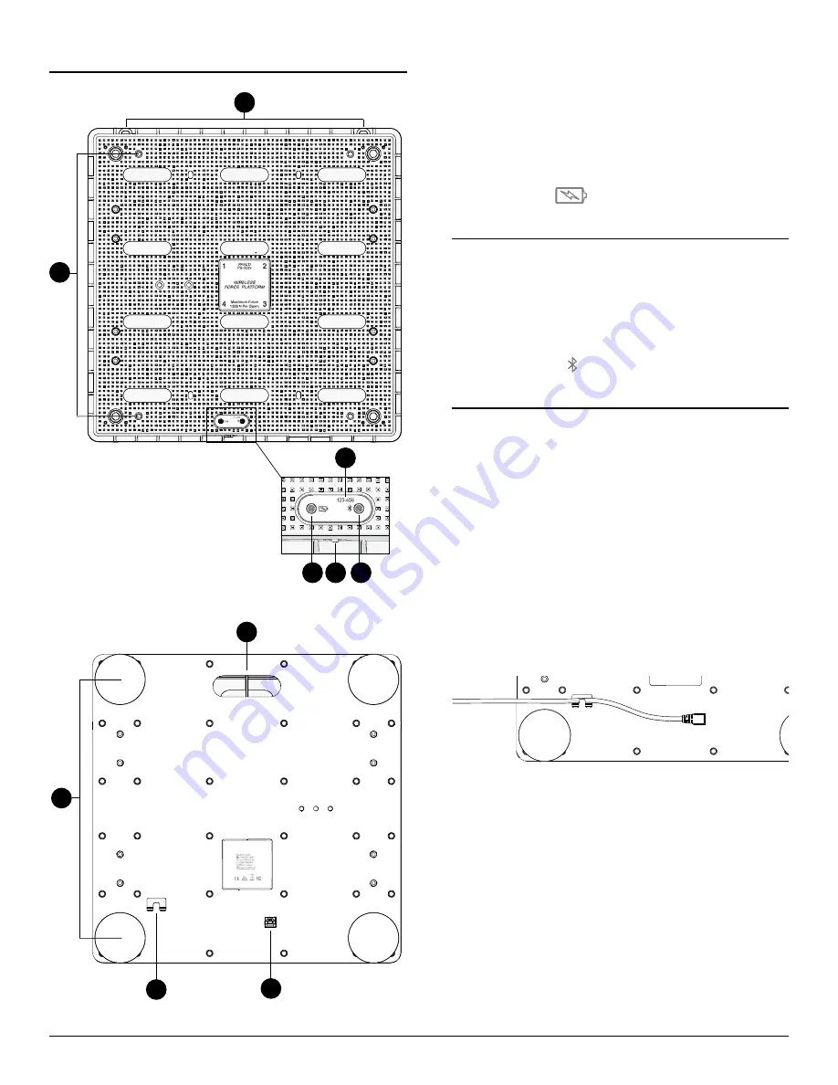
1. Wall mounting holes
Wall mounting holes
Use these holes to mount the force platform to a wall.
2. Handle mounting holes
Handle mounting holes
Use these holes to attach the Force Platform Handle Set (PS-2548)
to the platform.
3. Device ID
Device ID
Use to identify the sensor when connecting using Bluetooth.
4. Battery Status Light
Battery Status Light
Indicates the battery level and charging status.
LL
IGHT
SS
TATUS
Red, blink
Low battery level
Green, solid
Fully charged
Yellow, solid
Charging
5. Power Button
Power Button
Press and hold for one second to turn the sensor on or off.
6. Bluetooth Status Light
Bluetooth Status Light
Indicates the status of the Bluetooth connection.
LL
IGHT
SS
TATUS
Red, blink
Ready to pair
Green, blink
Paired
Yellow, blink
Remotely logging data
7. Carry handle
Carry handle
Use the handle to carry the Force Platform with one hand.
8. Feet and Force Beams
Feet and Force Beams
Each foot is attached to a force sensor and must be in contact
with the surface to measure force. The top of the foot must not
be in contact with the force platform. Adjust the height by turning
the feet by hand. You can also adjust the height from the top of
the platform by turning the hex bolts attached to each foot. The
force beams are identified by the label on the top of the platform.
9. Cable holder
Cable holder
Insert the USB cable through the recess to hold the cable in place.
10. USB Port
USB Port
Use with the USB cable to connect the platform to a USB wall
charger to charge the battery. Also use to send measurement
data to software when connected to a USB port of a computer or
mobile device (iOS devices not supported).
Wireless Force Platform | 3