


OS-8441
Wireless Diffraction Scanner
012-16243B
You can also check for an update by doing the following:
Go to the
Help
menu then click
Check for Updates
.
Select the menu icon
and select
Check for Updates
.
To update the firmware
The device contains firmware that controls how it
functions. It is important to make sure that your device has
the latest version of the firmware installed.
1. Connect the device to your software. It is
recommended to use a USB connection since
this will result in a faster update.
2. The software will prompt you if a firmware update
is available. Follow the instructions on the screen
if prompted. If you do not receive a prompt, the
firmware is up to date.
Connecting to Software
The device can be connected to software using USB or
Bluetooth.
To connect using USB
1. Connect the device to a computer using the USB
cable.
2. Open your PASCO software. The device
automatically connects with the software.
To connect using Bluetooth
1. Press and hold the power button until the battery
status LED turns on.
2. Open Capstone and click Hardware Setup.
3. Select the wireless device that matches your
device ID.
1. Press and hold the power button until the battery
status LED turns on.
2. Open SPARKvue and select Sensor Data.
3. Under Connected Devices, select the wireless
device that matches your device ID.
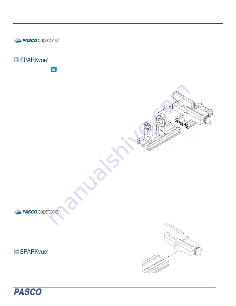
Experimental Setup
The Diffraction Scanner is designed to be used with a
PASCO laser, diffraction slits, and track (see Required
Equipment). The Diffraction Scanner can be mounted to
an optics track or a dynamics track using the included
Dynamics Track Optics Carriages. The setup works best
when the Diffraction Scanner is mounted at least 1 meter
from the diffraction slits (Figure 1).
Figure 1. Setup with laser and diffraction slits.
To mount to an optics track
1. Loosen the mounting screws without removing
the nut or the screw from the apparatus.
2. Insert the square nuts into the center slot of the
optics track with the aperture facing the track
3. Slide the Diffraction Scanner to the desired
position on the track then tighten the front and
rear mounting screws.
Figure 2. Inserting the Diffraction Scanner into an optics track.


