


®
M o d e l N o . A P - 8 2 1 4
E q u i p m e n t S e t - u p
3
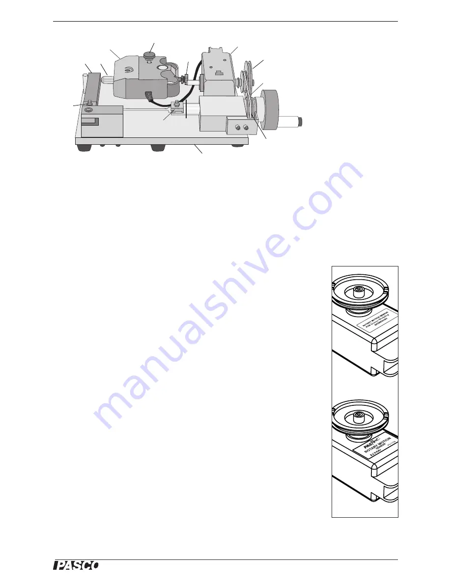
Equipment Set-up
1.
Attach the RMS to the apparatus platform
.
a.
Remove the rod clamp from the RMS.
b.
Place the three-step pulley onto the shaft of the RMS with the largest pulley
out. The three-step pulley should be on the “clockwise positive” side of the
RMS as illustrated (Figure 2).
c.
Place the RMS on the platform as illustrated (Figure 1). Use the two
thumbscrews to fasten the RMS to the platform from beneath.
d.
Seat the belt on the middle step of the three-step pulley and the groove on the
crankshaft.
2.
Attach the Force Sensor to the apparatus platform
.
a.
Remove the hook from the Force Sensor and replace it with the force sensor
attachment.
b.
Place the Force Sensor on the apparatus platform by inserting the post
through the support rod mount of the Force Sensor.
c.
Insert the long thumbscrew supplied with the Force Sensor through the hole
on the Force Sensor marked “Cart” and screw it into the tapped hole in the
apparatus platform.
d.
Tighten the setscrew in the support rod mount of the Force Sensor.
3.
Clamp down the apparatus (optional)
. Use a large C-clamp to clamp the Appa-
ratus Platform to the edge of your bench or table. One side of the platform has
three feet. In order to avoid bending the platform, position the clamp directly
over the center foot.
1. Rotary Motion Sensor (RMS)
2. Force Sensor
3. Force Sensor attachment
4. setscrew
5. Stress Strain platform
6. 3-step pulley
7. belt
8. groove
9. coupon clamps
10. lever arm
11. thumbscrew
1
2
3
4
11
6
7
8
9
10
9
5
Figure 1: Equipment Set-up
ScienceWorkshop
PASPORT
Figure 2: Three-step
pulley on the
“clockwise positive”
side of RMS