


Signal generator setup
To set up the 850 Universal Interface to act as a signal
generator, follow these steps based on the output port being
used.
Output Port 1:
1. Insert a banana patch plug cord into the ground port ( ) of
Output 1. Connect the other end of the cord to the ground
on the circuit board (or other device) which will be supplied
with a signal.
2. Insert a second banana patch plug cord into the signal
generator port (
) of Output 1. Connect the other end
of the cord to the positive lead on the circuit board (or other
device).
Output Port 2 or 3:
1. Connect the output port on the 850 Universal Interface to
one end of a BNC Function Generator Output Cable,
shrouded (UI-5129) or unshrouded (UI-5119). Ensure a
stable connection by tightening the BNC connector.
2. Connect the other ends of the 850 Universal Interface to
the circuit board or other device which will be supplied with
a signal. Make sure to attach the red lead to the positive
lead on the device and the black lead to the ground on the
device.
Signal generator configuration
For information on setting up the signal generator using PASCO
Capstone, consults the Capstone online help and search for
"Set up signal generator". The online help contains information
on how to configure various features of the signal generator,
including (but not limited to):
• Waveform
• Frequency
• Amplitude
• Phase Shift
• Voltage Offset
• Sweep Type
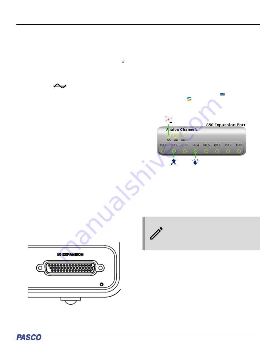
850 Expansion Port
The back of the 850 Universal Interface features a 44-pin
Expansion Port. This port can be used to connect the interface
to a breadboard, allowing the interface to process additional
input and output signals beyond those from the ports on the
front of the device.
The Expansion Port provides access to the following features:
• 3 additional analog input channels, labeled XA, XB, and XC
in PASCO Capstone.
• 8 digital input/output (I/O) channels, labeled I/O 1 through
I/O 8 in Capstone.
• An additional port for each of the three outputs of the signal
generator, outputting the same signals as the ports on the
front panel.
Connecting to the Expansion Port
To access the Expansion Port in PASCO Capstone, first connect
your 850 Universal Interface to Capstone as described in Set up
the hardware. From the Hardware Setup
panel, select the
Show Expansion Port
icon to display the Expansion Port
interface within the window. To hide the panel, click the Show
Expansion Port icon again.
The channels of the 850 Expansion Port can be connected as
follows:
• The analog channels can be configured as either a voltage
sensor or a peak amplitude sensor.
• The digital channels can be configured as either a digital
output or a digital input.
• All of the inputs and outputs of the Expansion Port are
available to use in Blockly programs within Capstone.
NOTE: The Expansion Port’s analog inputs have
a limit of 10 V. The digital I/O ports can be set to
output either 3.3 V or 5 V using the Digital
Output tool in Capstone. The Digital Output tool
can also be used to turn individual digital
outputs on or off.
Pin definitions
The 850 Expansion Port features 44 pins, each of which serves
a different function when connected. The pins on the expansion
port are numbered from right to left and from top to bottom. In
the top row, pin 1 is located on the far right and pin 15 is located
on the far left; in the middle row, pin 16 is on the right and pin 30
is on the left; and in the bottom row, pin 31 is on the right and
pin 44 is on the left.
The functions of each pin are as follows:
• Pins 1-8: Digital I/O ports (I/O 1 through I/O 8)
• Pins 9-13: PASPORT Serial Peripheral Interface (SPI) port
- Pin 9: SCLK
- Pin 10: MISO
Product Guide | 012-12355C
3


