Pasco Scientific OS-9255A Instruction Manual Download Page 14

11

012-07137B

Precision Interferometer

®

OS-9255A

PRECISION

INTERFEROMETER

-5

0

5

10

15

20

25

ADJUSTABLE MIRROR

MICHELSON, TWYMAN-GREEN

BE

AM

 S

PL

ITT

ER

MIC

HE

LS

ON

CO

MP

EN

SA

TO

R

MI

CH

EL

SO

N

18 mm FL

 LENS

VIEWING SCREEN

MICHELSON, TWYMAN-GREEN

1 div = 1 MICRON

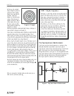
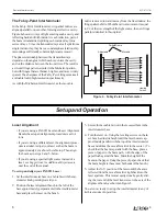
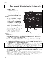
Experiment 1:  Introduction to Interferometry

Figure 1.1.  Michelson Mode Setup

Component holder

Compensator

(optional)

Movable

mirror

Beam

splitter

Viewing screen

Adjustable

mirror

Micrometer

knob

Adjustment

Thumbscrews

Lens

18mm FL

EQUIPMENT NEEDED:

– Basic Interferometer (OS-9255A)
– Laser (OS-9171)
– Laser Alignment Bench (OS-9172)
– Interferometer Accessories (OS-9256A)

Component Holder , (2) Calibrated Polarizers

Introduction

In general, an interferometer can be used in
two ways. If the characteristics of the light
source are accurately known (wavelength,
polarization, intensity), changes in the beam
path can be introduced and the effects on the
interference pattern can be analyzed. Experi-
ments 2 and 3 are examples of this procedure. On
the other hand, by introducing specific changes in
the beam path, information can be obtained
about the light source that is being used.

In this experiment, you'll use the interferometer to
measure the wavelength of your light source. If
you have a pair of polarizers, you can also
investigate the polarization of your source.

Procedure

Part I:  Wavelength

1.

Align the laser and interferometer in the Michelson mode, so an interference pattern is clearly visible on your
viewing screen. See 

Setup and Operation

 for instructions.

2.

Adjust the micrometer knob to a medium reading (approximately 50 µm). In this position, the relationship be-
tween the micrometer reading and the mirror movement is most nearly linear.

3.

Turn the micrometer knob one full turn counterclockwise. Continue turning counterclockwise until the zero on the
knob is aligned with the index mark. Record the micrometer reading.

  NOTE:

  When you reverse the direction in which you turn the micrometer knob, there is a small amount of

give before the mirror begins to move.  This is called mechanical backlash, and is present in all mechanical
systems involving reversals in direction of movement.  By beginning with a full counterclockwise turn, and then
turning only counterclockwise when counting fringes, you can eliminate errors due to backlash.

4.

Adjust the position of the viewing screen so that one of the marks on the millimeter scale is aligned with one of the
fringes in your interference pattern. You will find it easier to count the fringes if the reference mark is one or two
fringes out from the center of the pattern.

5.

Rotate the micrometer knob slowly counterclockwise.  Count the fringes as they pass your reference mark.
Continue until some predetermined number of fringes have passed your mark (count 

at least

 20 fringes).  As you

finish your count, the fringes should be in the same position with respect to your reference mark as they were
when you started to count. Record the final reading of the micrometer dial.

Summary of Contents for OS-9255A

Page 1: ...Instruction Manual and Experiment Guide for the PASCO scientific Models OS 9255A thru OS 9258A 012 07137B PRECISION INTERFEROMETER Includes Teacher s Notes and Typical Experiment Results...

Page 2: ...ion 4 Michelson Twyman Green Fabry Perot Setup and Operation 6 Tips on Using the Interferometer 9 Sources of Error Troubleshooting Experiments Experiment1 IntroductiontoInterferometry 11 Experiment 2...

Page 3: ...ghted and all rights reserved However permission is granted to non profit educational institutions for reproduction of any part of the manual providing the reproductions are used only for their labora...

Page 4: ...vide asimpleintroductiontothisimportantapplicationof interferometry Fabry Perot The Fabry Perot Interferometer is also an important contemporary tool used most often for high resolution spectrometry T...

Page 5: ...Ocatalogfordetails Additional Equipment Recommended TheOS 9256AInterferometerAccessoriesincludes RotatingPointer VacuumCell ComponentHolder Lens 18 mm Focal Length Lens 48 mm Focal Length GlassPlate 2...

Page 6: ...r Movable Mirror Adjustable Mirror Vacuum Cell Vacuum Pump withGauge Rotating Pointer Beam Splitter Compensator Plate Component Holder OS 9255A Precision Interferometer Lens 18 mm Fitted Case 2 Polari...

Page 7: ...m the two slits struck the screen a regular pattern of dark and bright bands appeared When firstperformed Young sexperimentofferedimportant evidence for the wave nature of light Young s slits can be u...

Page 8: ...he mirror a measured distance dm and counting m the number of times the fringe pattern is restoredtoitsoriginalstate thewavelengthofthelight canbecalculatedas 2dm m If the wavelength of the light is k...

Page 9: ...aser see Suggestions for Additional Experiments near the end of the manual To set up and align your PASCO Laser 1 Set the interferometer base on a lab table with the mi crometerknobpointingtowardyou 2...

Page 10: ...ks so that the beam is reflected to the fixed mirror Adjust the angle of the beam splitter as needed so that the reflected beam hits the fixed mirror near its center 4 There should now be two sets of...

Page 11: ...t s at least 12 inches from the edge of the interferometerbase Fringesshouldappearinthebright disk of the viewing screen Fine adjustments of L1 may be necessary to find the fringes A piece of white pa...

Page 12: ...he diffuser rather than on the viewing screen Just place the diffuser where you would normally place the viewing screen and look through it toward the interferometer Tips on Using the Interferometer F...

Page 13: ...nd back surfaces of the mirrors and beam splitter of ten cause minor interference patterns in the back ground of the main fringe pattern These background patterns normally do not move when the mirror...

Page 14: ...rferometerintheMichelsonmode soaninterferencepatternisclearlyvisibleonyour viewing screen See Setup and Operation for instructions 2 Adjustthemicrometerknobtoamediumreading approximately50 m Inthispos...

Page 15: ...ht 2dm N then average your results If you tried the Fabry Perot mode also calculate the wavelength independently for that data The same formula applies PartII 1 From your observations in step 1 of the...

Page 16: ...exactly 1 A graph of index of refraction versus pressure for a gas is shown in Figure2 1 Byexperimentallydeterminingtheslope the index of refraction of air can be determined at various pressures Proce...

Page 17: ...helightnowgoesthroughonelessoscillationwithin the cell This has the same effect on the interference pattern as when the movable mirror is moved towardthebeam splitterby1 2wavelength Asinglefringetrans...

Page 18: ...2 Placetherotatingtablebetweenthebeam splitter and movable mirror perpendicular to the optical path NOTE if the movable mirror is too far forward the rotating table won t fit You may need to loosen t...

Page 19: ...ction of air see Experiment 2 ng the index of refraction of the glass plate as yet unknown 0 the wavelength of your light source in vacuum and N the number of fringetransitionsthatyoucounted Carrying...

Page 20: ...pticalimperfections Thenremovetheviewing screenandreplacethelaserwiththespectrallight source Iffringesaren tvisiblewhenlookingintothe beam splitter proceedasfollows a Tape two thin pieces of wire or t...

Page 21: ...ate the Micrometer Knob fully IN before storing the Interferometer MicrometerCalibration The micrometer is calibrated before it is shipped How ever ifrecalibrationbecomesnecessary usethefollowing proc...

Page 22: ...03956 MovableMirror 003 03955 ComponentHolder 003 05161 Compensator 003 03958 InterferometerManual 012 05187 VacuumPump OS 8502 Component Part No VacuumCell 003 05162 RotationalPointer 003 05160 Fitt...

Page 23: ...imitingfactorsareplayinthesystemanduncertainty inourmicrometerposition 6 Losingcountoffringes andinexactpositioningofthe fringes relative to our reference mark 7 In order to interfere the two light be...

Page 24: ...e vacuum first then count the fringes as the vacuum was released The average slope starting at a guage reading of 60 was 3 462x10 6 0 9995 0 9996 0 9997 0 9998 0 9999 1 1 0001 1 0002 1 0003 1 0004 1 0...

Page 25: ...drews Prentice Hall 1960 is Thesecondtermisnegligibleforvisiblewavelengths and may be ignored Notes General It is often difficult to count large numbers of fringes due to eyestrain If you find this to...

Page 26: ...com web www pasco com Contacting Technical Support Before you call the PASCO Technical Support staff it wouldbehelpfultopreparethefollowinginformation If your problem is with the PASCO apparatus note...

Page 27: ...PrecisionInterferometer 012 07137B 24...

Reviews: