www.parweld.com
8
7.0 Fault Finding
Cutting problems
Description
Possible cause
Remedy
Torch cuts but not
adequately
1. Current set too low
2. Torch is being moved
too fast across work
piece
3. Oil or moisture in
torch
1. Increase
current
setting.
2. Reduce
cutting speed
3. Ensure
water trap
on rear of
machine
is empty
(disconnect
air supply
to allow it to
drain). Put
machine
in setting
mode Hold
torch 1/8
inch (3 mm)
from clean
surface while
purging and
observe oil
or moisture
buildup (do
not activate
torch)
Heavy dross on under-
side of plate
Cutting power is to low
Increase
cutting power
6.5 Cut Quality
Cut quality requirements differ depending on
application. Bevel angle may be a major factor when the surface
will be welded after cutting. Dross-free cutting is important when
finish cut quality is desired to avoid a secondary cleaning operation.
Rounding on the top edge of a cut due to wearing from the initial
contact of the plasma arc on the work piece. Dross is molten
material which is not blown out of the cut area and re-solidifies
on the plate. Top spatter is dross which accumulates on the top
surface of the work piece. Excessive dross may require secondary
clean-up operations after cutting. Improper standoff (the distance
between the torch tip and work piece) can adversely affect tip life
as well as shield cup life. Standoff may also significantly affect the
bevel angle. Reducing standoff generally results in a squarer cut.
A guide clip and crown stand off guide is available to maintain a
constant stand off height. The plasma gas stream swirls as it leaves
the torch. The purpose of the swirl is to maintain a smooth column
of gas. The swirl effect results in one side of a cut being squarer
than the other. Viewed along the direction of travel, the right side of
the cut is squarer than the left. If dross is present on carbon steel,
it is commonly referred to as either “high speed, slow speed, or top
dross”. Dross present on top of the plate is normally caused by too
great a torch to plate distance. Top dross is normally very easy to
remove and can often be wiped off with a welding glove. Slow speed
dross is normally present on the bottom edge of the plate. It can vary
from a light to heavy bead, but does not adhere tightly to the cut
edge, and can be easily scraped off. High speed dross usually forms
a narrow bead along the bottom of the cut edge and is very difficult
to remove. When cutting troublesome steel, it is sometimes useful to
reduce the cutting speed to produce slow speed dross. Any resultant
cleanup can be accomplished by scraping, not grinding. Starting the
Cut Edge Starting For edge starts, hold the torch perpendicular to
the work piece with the front of the tip on the edge of the work piece
at the point where the cut is to start. When starting at the edge of the
plate, do not pause at the edge and force the arc to “reach” for the
edge of the metal. Establish the cutting arc as quickly as possible.
6.6 Piercing
For piercing, angle the torch slightly too direct sparks
away from the torch until the pierce is complete. Start and complete
the pierce close to the cutting line and then continue the cut onto the
line. Hold the torch perpendicular to the work piece after the pierce
is complete. Clean spatter and scale from the outer nozzle and the
tip as soon as possible. A light coating of anti-spatter compound
may be applied to the outside to minimize the amount of scale which
adheres to it. Be careful not to get anti-spatter compound on the
torch tip or other parts.
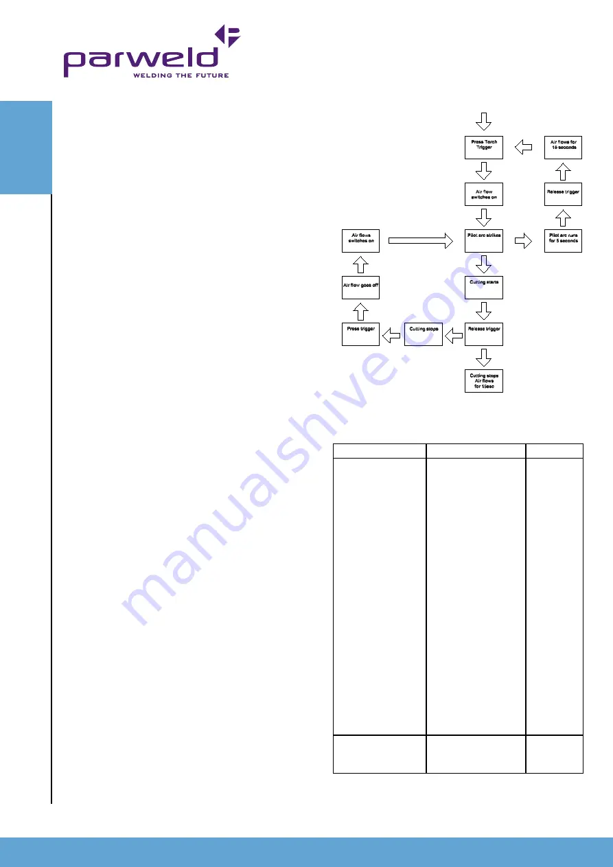
6.7 Operating the torch
With the torch in starting position press and hold the
trigger. After an initial gas purge, the main arc will come on. Once
on, the main arc remains on as long as the trigger switch is held
down, unless the torch is withdrawn from the work or torch motion
is too slow. If the cutting arc is interrupted, the cutting process must
be restarted. To shut off the torch simply release the trigger switch.
When the switch is released a 15 second post-flow will occur. If the
torch switch is closed during the post-flow, the cutting arc will restart
after switching off the air. Refer to the flow chart below for the
operating sequence.
Faul
t
FI
n
DI
n
G
Summary of Contents for XTP-63
Page 1: ...Operator Manual ISSUE 1 XTP 63...
Page 13: ...www parweld com 13...


