background image

CHAPTER 2 - GETTING STARTED: INSTALLING THE MEMORY CARD

16

ENGLISH


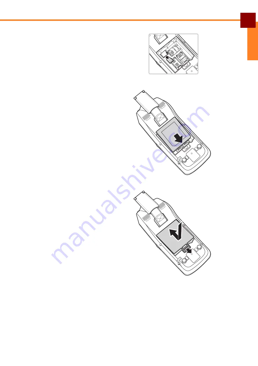
2. Insert the card into the memory 

card slot with contact side facing 
down, push it until it clicks into 
place.

3. Insert the battery. Re-orient the 

battery contact side to the 
bottom. Push the battery down 
until it clicks into place.

4. Replace the cover while pulling 

down the battery latch.

Summary of Contents for MF-2351

Page 1: ...F1 F2 F3 3DEF F4 2ABC 1 6MNO 5JKL 4 GHI 9WXYZ 8TUV 0 7PQRS ALPHA CANCEL CLEAR EHTER MF2351 All in One Mobile Terminal User s Manual ...

Page 2: ...TENTS 11 LED INDICATORS 12 Chapter 2 Getting Started 13 INSTALLING THE BATTERY 13 CHARGING THE BATTERY 15 INSTALLING THE MEMORY CARD 15 INSTALLING THE SIM CARD 17 INSTALLING THE SAM CARD S 19 ATTACHING THE STYLUS 21 INSTALLING THE PAPER ROLL 22 Chapter 3 Using the Terminal 24 POWERING THE DEVICE ON OFF 24 ENABLING BACKUP BATTERY 25 HOT SWAP MAIN BATTERY 25 INITIAL SETUP 26 CALIBRATING THE TOUCH SC...

Page 3: ...39 LEFT ARROW RIGHT ARROW BACKSPACE 40 Chapter 5 Configuring Utilities Settings 41 MSR 42 PRINTER 45 WLAN 46 BARCODE SCANNER 47 RFID 51 IC CARD READER 52 CAMERA 53 GPS 54 GENERAL SETTING 56 BLUETOOTH 57 GSM 59 GPRS 63 Chapter 6 SPECIFICATIONS 67 OPTIONAL FEATURES 68 ...

Page 4: ... the product unplug it from the electrical outlet and request service from a service partner under the following conditions The power cord or plug is damaged Liquid has been spilled into the product An object has fallen into the product The product has been exposed to rain or water The product has been dropped or damaged The product does not operate normally when you follow the operating instructi...

Page 5: ... battery Do not incinerate or heat the battery This will cause the insulator to melt damage the gas release vent and cause loss of safety function or electrolyte ignition Above mentioned matters will cause battery to rupture generate heat or cause smoke and flame Do not use near high temperature areas Do not use or leave battery near fire stove or heated areas of more than 80 C to avoid melting of...

Page 6: ...flame Do not insert battery into a microwave or high pressure container This may cause battery to deform generate heat or cause smoke or flame because of sudden heat intense pressure or damage to the sealing condition of the battery Do not put leaked battery near fire If liquid leaks from the battery or the battery give outs a bad smell do not leave battery near flammable objects Otherwise the ele...

Page 7: ...ted under international copyright laws with all rights reserved Neither this manual nor any of the material contained herein may be reproduced without written consent of Partner Tech Corp DISCLAIMER The information in this document is subject to change without notice The manufacturer makes no representations or warranties with respect to the contents in this document and specifically disclaims any...

Page 8: ...rence that may cause undesired operation This device has been tested and found to comply with the limits for a Class B digital device pursuant to Part 15 of the FCC Rules These limits are designed to provide reasonable protection against harmful interference in a residential installation This device generates uses and can radiate radio frequency energy and if not installed and used in accordance w...

Page 9: ... the measurement methods and procedures specified in OET Bulletin 65 Supplement C WEEE Notice The WEEE logo on the product or on its box indicates that this product must not be disposed of or dumped with your other household waste You are liable to dispose of all your electronic or electrical waste equipment by relocating over to the specified collection point for recycling of such hazardous waste...

Page 10: ...adio or television reception which can be determined by turning the equipment off and on the user is encouraged to try to correct the interference by one or more of the following measures Reorient or relocate the receiving antenna Increase the separation between the equipment and receiver Connect the equipment into an outlet on a circuit different from that to which the receiver is connected Consu...

Page 11: ...standards GPRS WCDMA CDMA2000 PRODUCT OVERVIEW FRONT AND BACK No Item Description 1 RFID reader RFID reader module 2 Thermal printer Thermal printer module for printing purposes 3 3 5 LCD screen Mobil terminal main screen 4 Speaker Speaker units 5 Camera 3 0 megapixel digital camera module 6 LED light LED light for the digital camera module 7 Battery Main battery compartment 8 Handstrap The strap ...

Page 12: ...daptor 2 6 Function keys Software programmable function keys 3 RS232 connector Connects to a RS232 cable for data transfer purposes 4 Fingerprint sensor Fingerprint sensor module to scan fingerprints 5 Earphone jack Connects to an earphone 7 USB port Connects to a mini USB cable for data transfer purposes 1 3 2 5 4 7 6 ...

Page 13: ...CT OVERVIEW 10 ENGLISH TOP AND BOTTOM No Item Description 1 Barcode scanner window Aim this scanner window to read barcodes 2 IC Card IC Card module reads data from smartcards 3 MSR MSR module reads data from magnetic cards 1 2 3 ...

Page 14: ...l RFID ISO 14443 A B WLAN 802 11 b g GPRS WCDMA CDMA2000 microSD card reader read write GPS ISO7816 EMV2000 Level 1 2 IC card reader Fingerprint sensor 3 0 megapixels autofocus camera DC jack earphone microphone jack speaker integrated microphone vibrator motor reset button MF 2351 mobile terminal AC adaptor Power cord Battery Stylus and strap USB cable F1 F2 F3 3DEF F4 2ABC 1 6MNO 5JKL 4 GHI 9WXY...

Page 15: ...RS MF 2351 has 4 LED indicators located across the top of the display The first LED is the charging indicator The light will blinks during charging and lit when the battery is full The last three are software programmable Charging indicator Software programmable ...

Page 16: ...2 Getting Started INSTALLING THE BATTERY 1 Release the strap Pull the lower end of the strap downward 2 Pull down the battery latch and open the cover 3 Insert the battery Re orient the battery contact side to the bottom Push the battery down until it clicks into place ...

Page 17: ...CHAPTER 2 GETTING STARTED INSTALLING THE BATTERY 14 ENGLISH 4 Replace the cover while pulling down the battery latch 5 Replace the hand strap ...

Page 18: ... The leftmost LED light will blinks during charging and lit red when the battery is full INSTALLING THE MEMORY CARD The mobile terminal s internal space storage can be used to store user files such as snapshots from the camera module and various applications This storage can be expanded with a microSD memory card sized up to 64GB 1 Open the battery compartment cover and remove the battery 1 2 ...

Page 19: ...the card into the memory card slot with contact side facing down push it until it clicks into place 3 Insert the battery Re orient the battery contact side to the bottom Push the battery down until it clicks into place 4 Replace the cover while pulling down the battery latch ...

Page 20: ...M CARD The mobile terminal features a SIM card slot SIM card is required for internet access 1 Open the battery compartment cover and remove the battery 2 Release the card slot by pulling it left and upward 3 Slide the SIM card into the slot 4 Close it back and push toward right ...

Page 21: ... STARTED INSTALLING THE SIM CARD 18 ENGLISH 5 Insert the battery Re orient the battery contact side to the bottom Push the battery down until it clicks into place 6 Replace the cover while pulling down the battery latch ...

Page 22: ...rd is used for authentication purposes It is commonly needed by devices performing secure transactions and payment applications 1 Open the battery compartment cover and remove the battery 2 Release the slot by pulling to the top and upward 3 Slide the SAM card into the slot 4 Close it back and push toward bottom ...

Page 23: ...STARTED INSTALLING THE SAM CARD S 20 ENGLISH 5 Insert the battery Re orient the battery contact side to the bottom Push the battery down until it clicks into place 6 Replace the cover while pulling down the battery latch ...

Page 24: ... THE STYLUS The stylus is the standard input tool to interact with the terminal s touch screen 1 Fasten one end of the stylus strap to the stylus 2 Fasten the other end of the stylus strap to the terminal s backside 3 Insert the stylus into its slot when not in use 1 2 ...

Page 25: ...thermal printer module provides a means to print out data from payment applications 1 Pull up the lever located at the top of the device to eject the printer cover 2 Insert the paper roll into place Refer to the illustration for the correct positioning of the paper roll 3 Close the cover firmly ...

Page 26: ...CHAPTER 2 GETTING STARTED INSTALLING THE PAPER ROLL 23 ENGLISH ...

Page 27: ...ce has three different power states Off Standby and On Below table shows how to power on off enter Standby mode and wake up from Standby mode Power state Procedure Off On Press and hold Power button On Off Press and hold Power button tap Shutdown on the screen On Standby Press Power button Standby On Press Power button Power button ...

Page 28: ...Put switch towards the left to enable backup battery HOT SWAP MAIN BATTERY When backup battery is enabled hot swap of the main battery is possible To perform the hotswap procedure 1 Press and hold Power button then tap Remove Battery on the screen or 2 Tap Remove Battery icon directly on the desktop Shutdown will power down the terminal Reboot will restart the operating system and clear the memory...

Page 29: ...r any other tapping tool It can be repeated many times as necessary whenever the tapping is becoming inaccurate 3 From Start Menu Settings Control Panel double tap Stylus 4 Double tap on the grid to calibrate the taps 5 Select the Calibration tab to calibrate the tap zone 6 The device will show a plus sign at several different places 7 Tap the stylus point at the plus sign to complete the procedur...

Page 30: ...HE DATE AND TIME Adjust the date and time of the terminal to provide accurate operation The time zone can be also set accordingly To set the date and time 1 Open the Start Menu Settings Control Panel 2 Double tap the Date Time 3 Set the date and time accordingly 1 ...

Page 31: ...G THE SCREEN BRIGHTNESS The terminal screen s brightness can be adjusted to suit the environment To adjust the screen brightness 1 Open the Start Menu Settings Control Panel 2 Double tap the Brightness 3 Set the value anywhere between 1 dimmest and 9 brightest 2 3 ...

Page 32: ... Taskbar 1 Select Start Menu Settings 2 Select Taskbar and Start Menu 3 Options available for Taskbar are Always on top Auto hide and Show Clock Always on top means the Taskbar will be displayed all the time If disabled running an application may block the Taskbar Show Clock will display the clock at the lower right corner when enabled ...

Page 33: ...rminal Function buttons programmable through applications Cancel button cancel current input Clear button move the cursor left one character and erase any text Enter button confirm and submit current input Numeric buttons input numbers Press ALPHA once to input the alphabets Press ALPHA again to input the alphabets in capital Numeric buttons Power button Function buttons Cancel button Clear button...

Page 34: ...CHAPTER 3 USING THE TERMINAL USING THE KEYPAD 31 ENGLISH ...

Page 35: ...ed by a dotted circle on the screen Hold it until the circle is completed There are two modes of operation for the stylus Keyboard and Transcriber KEYBOARD MODE When in Keyboard mode a mini keyboard will be displayed at the bottom of the screen Typing is simply done by tapping the character on the mini keyboard To activate this mode 1 Tap the Keyboard icon at the right side of Taskbar 2 Select Key...

Page 36: ...HE STYLUS KEYBOARD MODE 33 ENGLISH Hide the input panel to return to normal operation and maximize the screen estate To hide the input panel 1 Tap the Keyboard icon on the right side of Taskbar 2 Select Hide Input Panel ...

Page 37: ...e is Transcriber a free form writing mode In this form user can use the stylus to gesture handwriting directly on the screen To activate this mode 1 Tap the Keyboard icon at the right side of the Taskbar 2 Select Transcriber 3 A row of icons will appears at the bottom side of the screen ...

Page 38: ...ection Select a direction that represents the angle in the recognition process The first option is the default The second option is used for writing that slants up to the right The third option is used for writing that slants down to the left The last option changes the screen orientation for recognition between portrait and landscape ...

Page 39: ...splayed every time the Transcriber mode is activated Sound If selected sound cue will be played as feedback Recognition Delay Set the delay to shorten or lengthen the delay for handwriting recognition Center position is about a second worth of delay Add Space After Automatically add a space after recognition ...

Page 40: ...ine tuned to match a certain handwriting style and shorten the recognition process Pen Set the width and color of ink to be displayed on the screen during handwriting input Tap the LSS to open this menu File Open to import the LSS file File Save to save the configured LSS file for future use or for other terminals ...

Page 41: ...g The terminal will recognize any character written with the stylus directly on the touch screen Tap the Keyboard to display the mini keyboard Tap Recognition to switch between modes Available modes are a alpha mode The default mode and the optimum method for handwriting recognition 123 numeric mode Numerals and some letters allowed in this mode A uppercase mode Automatically capitalizes all lette...

Page 42: ... USING THE STYLUS TRANSCRIBER MODE 39 ENGLISH SPACE RETURN Insert a space at the cursor position Tap spc to insert a space Insert a return character at the cursor position Tap Return to insert a Return character ...

Page 43: ...cursor one space to the left of the cursor position Tap Left to move the cursor left Right Arrow Move the cursor one space to the right of the cursor position Tap Right to move the cursor right Backspace Move the cursor one space back and erase any text Tap Backspace to move the cursor back and erase any text ...

Page 44: ... settings To access this utility tap Start Menu Control Panel Setting Manager There are five buttons under the Test Utilities RFID wireless tag reader module test utility ICCard smartcard reader module test utility Printer thermal printer module test utility Camera digital camera module test utility GPS Global Positioning System module test utility ...

Page 45: ... all possible recording methods currently in use This is the default tab when you open Setting Manager Under Key Wedge Enable MSR key wedge will send the reading result from MSR module to the currently active application Enable 1D BCR key wedge will send the reading result from barcode module to the currently active application Tap MSR Setting to open MSR setting window ...

Page 46: ...inel for each track and the end sentinel The default values are set to the ISO standard track 1 track 2 track 3 end sentinel Input the Prefix Suffix to add beginning ending for package and each tracks accordingly Tap Default to reset the configurations back to the factory default Tap Apply to save the current configurations for the MSR module Test read a magnetic card 1 Tap Test to open the test w...

Page 47: ...CHAPTER 5 CONFIGURING UTILITIES SETTINGS MSR 44 ENGLISH 2 Swipe the card through the MSR module 3 Data will appear in the window for a successful read ...

Page 48: ...ore starting any print testing procedure Please refer to the Installing the Paper Roll how to install one Tap Printer to open Printer setting window Configuring Printer module Print 16x16 24x24 32x32 48x48 Set the printout density 16x16 is the coarsest while 48x48 is the densest Type in the desired print head depth in the field then tap Set Print Depth This will affect the printout saturation Load...

Page 49: ...ireless local network This module complies to the 802 11b g standard Tap the WLAN tab on the Setting Manager to open WLAN setting window Configuring WLAN module Tap Power On to power up the WLAN module Tap Power Off to power it down Power on WLAN when bootup the terminal will automatically power up the WLAN module during boot up otherwise it will need to be manually activated ...

Page 50: ...RCODE SCANNER 47 ENGLISH BARCODE SCANNER Located at the topside of MF 2351 the barcode scanner module supports many of the popular barcode formats currently used worldwide Tap 1D BCR setting on the Modules tab to open the barcode setting window ...

Page 51: ...ix add a suffix at the end of a barcode Code ID determine whether to transmit the code ID or not Tap Config to open the recognition setting for various barcode types supported by MF2351 Tap Default to reset the configuration to factory setting Tap Apply to save the current configuration Barcode configuration Select the appropriate barcode types The selected items are marked with _ icon Tap Default...

Page 52: ...5 CONFIGURING UTILITIES SETTINGS BARCODE SCANNER 49 ENGLISH Test read a barcode 1 Tap Test to open the test window 2 Aim the barcode reader window at a barcode 3 Press the Barcode Trigger button barcode trigger ...

Page 53: ...CHAPTER 5 CONFIGURING UTILITIES SETTINGS BARCODE SCANNER 50 ENGLISH 4 Data will appear in the window for a successful read ...

Page 54: ...B standard Tap the RFID to open RFID setting window Configuring the RFID module Open start the RFID reader Close shutdown the RFID reader AB Key choose the type of key to access between A and B for Mifare card Key define the key value Enter the value in hex Block select the block to access UID scan the RFID tag identification Read data fetch data from the RFID tag Write data send data to the RFID ...

Page 55: ...ules tab to open the IC Card setting window Configuring IC Card module Slot choose the slot to access IC Card check check the selected IC card The result will be displayed on the dialog box IC Card reset reset the selected IC card IC Card command send command to IC card for various tasks specific to the selected IC card The results will be displayed on the dialog box IC Card close close the access...

Page 56: ...mera can perform equally during day and night time Tap Camera on the Modules tab to open Camera setting window Configuring Camera module Preview display the viewport on screen for preview purpose Snap take a snapshot Close close the camera window and return to the Setting Manager LightOn turn on the camera light to help in darker ambience LightOff turn off the camera light ...

Page 57: ...m module shows the current location of MF 2351 Configuring GPS module 1 Tap GPS to open the GPS setting window 2 Notice a message will appear when barcode scanner module is active Skip to step 4 if this message does not appear 3 Turn off Enable 1D BCR key wedge to use the GPS test utility ...

Page 58: ...APTER 5 CONFIGURING UTILITIES SETTINGS GPS 55 ENGLISH 4 Dialog box will appear to show results from GPS module Port Open start the GPS module Port Close shutdown the GPS module Clear empty the dialog box ...

Page 59: ...ow displays the general setting and display additional information such as OS version and serial number To open it tap Other tab on the Setting Manager Configuring general setting Enable setting manager tray display the Setting Manager icon on the Taskbar for easy access Apply save the changes ...

Page 60: ...BLUETOOTH Mobile terminal can connect to other devices through Bluetooth connection Configuring Bluetooth 1 Tap Bluetooth from the Start Control Panel 2 Tap Scan Device to start discovering nearby Bluetooth connection 3 Available Bluetooth connection s will appear ...

Page 61: ...CHAPTER 5 CONFIGURING UTILITIES SETTINGS BLUETOOTH 58 ENGLISH 4 Right tap to establish a connection and tap Trusted 5 Tap Yes to connect with a password protected connection 6 Input the PIN and tap OK ...

Page 62: ...net connection through a GSM Global System for Mobile device To create an internet connection using GSM device 1 Tap Start Setting Network and Dial up Connections 2 Double tap Make New Connection 3 Type in the name for the connection and select Dial Up Connection Tap Next to continue 4 Select ztemtmodem ...

Page 63: ...CHAPTER 5 CONFIGURING UTILITIES SETTINGS GSM 60 ENGLISH 5 Tap Configure 6 Set Baud Rate to 115200 7 Tap Call Options ...

Page 64: ...IES SETTINGS GSM 61 ENGLISH 8 On Extra Settings insert this command cdgcont 1 ip internet 9 Tap OK to complete the configure step 10 Tap Next to continue 11 Set these settings Country 886 Area code 2 Phone number 99 12 Tap Finish ...

Page 65: ...CHAPTER 5 CONFIGURING UTILITIES SETTINGS GSM 62 ENGLISH 13 Double tap on the newly created connection 14 Type in the login information then tap Connect ...

Page 66: ...nection through a GPRS General Packet Radio Service device To create an internet connection using GPRS device 1 Tap Start Setting Network and Dial up Connections 2 Double tap Make New Connection 3 Type in the name for the connection and select Dial Up Connection Tap Next to continue 4 Select Hayes Modem on COM2 ...

Page 67: ...CHAPTER 5 CONFIGURING UTILITIES SETTINGS GPRS 64 ENGLISH 5 Tap Configure 6 Set Baud Rate to 115200 7 Tap Call Options ...

Page 68: ...TINGS GPRS 65 ENGLISH 8 On Extra Settings insert this command cdgcont 1 ip internet 9 Tap OK to complete the configure step 10 Tap Next to continue the setting 11 Set these settings Country 886 Area code 2 Phone number 99 1 12 Tap Finish ...

Page 69: ...CHAPTER 5 CONFIGURING UTILITIES SETTINGS GPRS 66 ENGLISH 13 Double tap on the newly created connection 14 Type in the login information then tap Connect ...

Page 70: ...ard x2 Keypad Alphanumeric IC Card ISO7816 EMV2000 Level 1 2 certified Camera 3 0 Megapixels autofocus with light Other DC jack earphone and microphone jack speaker integrated microphone vibrator motor reset button Battery Main rechargeable li ion battery 7 4V 2000mAh Hotswap rechargeable polymer battery 3 7V 100mAh Environmental Operating temperature 0 to 40 C Storage temperature 20 to 70 C Dimen...

Page 71: ...URES Specification subject to change without prior notice Item Specifications Barcode 1D 2D RFID ISO 14443 A B Telecom Standards GPRS WCDMA CDMA2000 GPS Channels 50 Frequency L1 Signals GPS C A Code Fingerprint Sensor Image sensor 256 x 360 sensors array format 508 DPI ...

Page 72: ......

Reviews: