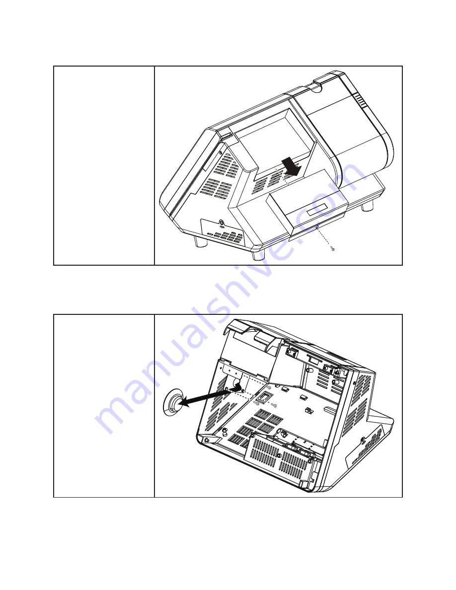
Partner Tech International PT-6200 Service Manual Download Page 63

55

Customer Display

Remove the screw.

1. 

Disconnect the cables 

2. 

from the mainboard.

Slide out the customer 

3. 

display.

Speaker

Before proceeding, remove 

the following FRUs.

“Front Panel” on page 55.

• 

“Mainboard” on page 56.

• 

Disconnect the cables on 

1. 

the mainboard.

Remove the three screws 

2. 

from the speaker bracket.

Remove the speaker.

3. 

Summary of Contents for PT-6200

Page 1: ...PT 6200 Service Manual...

Page 2: ......

Page 3: ...ipment generates uses and can radiate radio frequency energy and if not installed and used in accordance with the instructions may cause harmful interference to radio communications However there is n...

Page 4: ...3 Installing Drivers and Software This chapter provides information on installing drivers for supported operating systems Chapter 4 Locating the Problem Refer to this chapter to locate the failing par...

Page 5: ...evice 15 OnChip PCI Device 16 SuperIO Device 17 Power Management Setup 18 PnP PCI Configurations 20 IRQ Resources 21 PC Health Status 22 Frequency Voltage Control 23 Other BIOS Options 24 CHAPTER 3 IN...

Page 6: ...nectors 48 CHAPTER 5 REPLACING FIELD REPLACEABLE UNITS FRUs 49 Safety and precautions 49 Before you begin 50 Replacing parts 50 Front Panel 51 MSR 51 Mainboard 52 Hard drive 53 Thermal Printer 54 Cust...

Page 7: ...ripherals menu 14 Figure 3 7 VIA OnChip IDE Device submenu 15 Figure 3 8 VIA OnChip PCI Device submenu 16 Figure 3 9 SuperIO Device submenu 17 Figure 3 10 Power Management Setup menu 18 Figure 3 11 Pn...

Page 8: ...vi...

Page 9: ...are described Unpacking the machine on page 1 Identifying components on page 2 Unpacking the machine It is a good idea to save the packaging materials and shipping box in case that machine needs to b...

Page 10: ...This section describes the parts and connectors on the machine Front right view 1 5 2 Figure 1 2 Front right view of the machine Component Description 1 Power Button 2 10 4 inch TFT LCD 5 wire Resist...

Page 11: ...3 Rear view 1 Figure 1 3 Rear view Component Description 1 2x20 VFD customer display 2 Printer paper exit 3 80mm thermal receipt printer 4 Printer button 3 2 4...

Page 12: ...T E D I O connectors Figure 1 4 PT 6200 I O connectors 4 1 2 3 5 6 7 8 9 Connector Description 1 COM4 port 2 COM2 port 3 LAN port RJ 45 4 12V power connector 5 PS 2 keyboard port 6 RJ 11 cash drawer p...

Page 13: ...age 1 8 PnP PCI Configurations on page 2 0 PC Health Status on page 2 2 Frequency Voltage Control on page 2 3 Other BIOS Options on page 2 4 About the Setup Utility The BIOS Setup Utility enables you...

Page 14: ...menu F1 Displays a screen that describes all key functions F5 Loads previously saved values to CMOS F6 Loads a minimum configuration for troubleshooting F7 Loads an optimum set of values for peak perf...

Page 15: ...the highlight to other options When an option is highlighted execute the option by pressing Enter Some options lead to pop up dialog boxes that prompt you to verify that you wish to execute that optio...

Page 16: ...ected by the system at start up time These are display only fields You can not make changes to these fields Base Memory This field displays the amount of conventional memory detected by the system dur...

Page 17: ...pensation is a feature whereby the HDD uses a stronger magnetic field to write data in sectors that are closer to the center of the disk In CAV recording in which the disk spins at a constant speed th...

Page 18: ...m will boot but access to Setup will be denied if the correct password is not entered at the prompt APIC Mode This item is used to activate the ACPI Advanced Configuration and Power Management Interfa...

Page 19: ...For DRAM 64 MB This item is only required if you have installed more than 64 MB of memory and you are running the OS 2 operating system Otherwise leave this item at the default The default setting is...

Page 20: ...the DRAM Timing Selectable is set to Manual this field is adjustable When synchronous DRAM is installed the number of clock cycles of CAS latency depends on the DRAM timing The default value is 2 5 A...

Page 21: ...When the CPU temperature reaches a factory preset level a thermal monitoring mechanism will be enabled following the appropriate timing delay specified in this field With the thermal monitoring enable...

Page 22: ...y The factory setting is None IMPORTANT The voltage for the COM ports is set at None at the factory However for example to provide power to an installed customer display this setting must be set at 12...

Page 23: ...mainboard supports UltraDMA technol ogy which provides faster access to IDE devices If you install a device that supports UltraDMA change the appropriate item on this list to Auto You may have to ins...

Page 24: ...ing is Enabled USB Keyboard Support Enable this item if you plan to use a keyboard connected through the USB port in a legacy operating system such as DOS that does not support Plug and Play The defau...

Page 25: ...enable or disable built in IR Infrared transmission feature The default setting is Normal Option Description Normal Disable IR transmission feature and disable standard COM2 settings a default setting...

Page 26: ...he power saving modes and hard disk timeouts If this item is set to Max Saving power saving modes occur after a short timeout If this item is set to Min Saving power saving modes occur after a longer...

Page 27: ...hold the power button down for four seconds to cause a software power down The default setting is Instant Off CPU THRM Throttling This item allows you to select the CPU THRM Throttling rate The defaul...

Page 28: ...g the system dynamically allocates resources to plug and play devices as they are required If you cannot get a legacy ISA Industry Standard Architecture expansion card to work properly you might be ab...

Page 29: ...IRQ 15 assigned to PCI Device Item Help Move Enter Select PU PD Value F10 Save ESC Exit F1 General Help F5 Previous Values F6 Fail Safe Defaults F7 Optimized Defaults IRQ Resources This menu can only...

Page 30: ...ot configurable PC Health Figure 3 13 Status menu These items display the current status of system temperatures and power status Phoenix AwardBIOS CMOS Setup Utility PC Health Status Current CPU Tempe...

Page 31: ...treme values spikes of the pulses creates EMI Electro magnetic Interference The Spread Spectrum function reduces the EMI generated by modulating the pulses so that the spikes of the pulses are reduced...

Page 32: ...that lets you load optimized defaults for all appropriate items in the Setup Utility The optimized defaults place demands on the system that may be greater than the performance level of the component...

Page 33: ...ress any key to continue 4 Press any key You are prompted to confirm the password Confirm Password 5 Type the password again and press Enter or press Enter if you are deleting a password that is alrea...

Page 34: ...26 C H A P T E R 2 B I O S S E T U P...

Page 35: ...hipset Graphics Driver on the page 3 0 Audio driver on the page 3 2 LAN Driver on the page 3 4 Touch Screen Driver on the page 3 6 Driver auto installation Use an external CD ROM drive to install the...

Page 36: ...Utility updates the Windows XP 2000 INF files so that the Intel chipset is correctly configured Follow these instructions to install the chipset software Browse to the DRIVER chipset Intel Inf folder...

Page 37: ...adMe Information then click Next 4 The Intel Chipset Software Utility files are installed to the system When prompted to restart select 5 Yes I want to restart my computer now Then click Finish to res...

Page 38: ...cs Driver This utility installs the Intel Extreme Graphics 2 drivers for Windows XP 2000 To install the drivers Browse to the DRIVER VGA intel Win2K_XP folder 1 Double click the executable file The fo...

Page 39: ...31 Read the License Agreement then click 4 Yes to begin installation When installation is completed select 5 Yes I want to restart my computer now Then click Finish to restart the system...

Page 40: ...iver The Realtek Audio Driver Setup Program supports Windows XP 2000 Refer to the following to install the drivers Browse to the DRIVER SOUND RealTek folder 1 Double click the executable file The foll...

Page 41: ...33 Click 4 Yes I want to restart my computer now and then click Finish...

Page 42: ...R E LAN Driver The network driver support Windows XP 2000 Refer to the following to install the drivers Browse to the DRIVER LAN RealTek folder 1 Double click the executable file The following screen...

Page 43: ...35 When installation is completed click 4 Finish...

Page 44: ...uch Screen Driver Refer to the following to install the touch screen driver Browse to the DRIVER Touch eGalax folder 1 Double click setup exe The following screen appears Click 2 Next to continue Chec...

Page 45: ...37 System will give you a warning click 4 Ok to continue Check the box for 5 None and then click Next to continue Uncheck the box for 6 Support Mulit Monitor System and then click Next to continue...

Page 46: ...38 C H A P T E R 3 I N S TA L L I N G D R I V E R S A N D S O F T W A R E Click 7 Next to continue Click 8 Next to continue...

Page 47: ...rating the touchscreen Follow these instructions to calibrate the touchscreen using the TouchKit application Launch the TouchKit application from the Windows desktop by clicking on 1 Start Programs To...

Page 48: ...S O F T W A R E Click the 3 4 Points Calibrattion button Use your finger to touch the blinking X Symbol on the screen until stop blinking 4 Click 5 OK to complate the 4 points calibration NOTE You ma...

Page 49: ...the page 4 6 Mainboard connectors on the page 4 7 Inverter connectors on the page 4 8 General checkout guidelines Use the following procedure to troubleshoot problems Identify as many symptoms as poss...

Page 50: ...rective Procedure LCD backlight is not working but text is still visible on screen Reseat the LCD cable 1 Reseat the inverter cables 2 Replace the inverter cables 3 Replace the inverter 4 LCD backligh...

Page 51: ...Procedure Power shuts down unexpectedly Cannot turn the system on Reseat the power AC adapter cable 1 Reseat the power AC adapter 2 Replace the mainboard 3 Cannot turn the system off Hold down the pow...

Page 52: ...Peripheral device symptoms Symptom Corrective Procedure USB ports do not work COM ports do not work Reseat the I O cable 1 Reinstall the drivers 2 Replace the mainboard 3 Boot symptoms Symptom Correct...

Page 53: ...jumpers are to set system configuration options When setting the jumpers be sure the shunts jumper caps are placed on the correct pins CAUTION Ensure that the system is turned off before you change a...

Page 54: ...lt BANIAS 2 3 closed DOTHAN J8 Keyboard Voltage Select 1 2 closed 5Vcc 2 3 closed default Standby 5V J14 COM4 Voltage Select 1 2 closed default Normal 2 3 closed 5Vcc J15 COM3 Jumper Voltage 1 2 close...

Page 55: ...r to LCD panel connector to speaker connector to thermal printer connect to touch panel connect to HDD power connector to MSR connector to power button connector to power LED connect to IDE HDD connec...

Page 56: ...48 C H A P T E R 4 L O C AT I N G T H E P R O B L E M Inverter connectors Figure 4 4 Inverter connectors connector to mainboard connector to LCD...

Page 57: ...cautions Computer components and electronic circuit boards can be damaged by discharges of static electricity Working on computers that are still connected to a power supply can be extremely dangerous...

Page 58: ...n get into the PT 6200 components and may cause malfunction Adequate lighting and proper tools can prevent you from accidentally damaging the internal components Most of the electrical and mechanical...

Page 59: ...ront Panel Remove the three screws 1 Open the front panel 2 MSR Before proceeding remove the following FRUs Front Panel on page 55 Disconnect the cables 1 Remove the screw 2 Slide up and remove the 3...

Page 60: ...efore proceeding remove the following FRUs Front Panel on page 55 Disconnect the cables on 1 the mainboard Remove the three screws 2 from the mainboard tray Remove the mainboard 3 tray Remove the 5 sc...

Page 61: ...53 Hard drive Remove the screw 1 Pull out the hard drive tray 2 Disconnect the power cable and 3 data cable from the hard drive Remove the four screws then 4 remove the hard drive out from the tray...

Page 62: ...I N G F I E L D R E P L A C E A B L E U N I T S F R U s Thermal Printer Press the release and open the printer cover 1 Find the screw in the center of the 2 printer Remove the screw 3 Disconnect the...

Page 63: ...from the mainboard Slide out the customer 3 display Speaker Before proceeding remove the following FRUs Front Panel on page 55 Mainboard on page 56 Disconnect the cables on 1 the mainboard Remove the...

Page 64: ...oard Remove the seven screws 2 from the LCD panel tray Remove the tray 3 Disconnect the cable from 4 the inverter Remove the four screws 5 Remove the LCD panel 6 Inverter Before proceeding remove the...

Page 65: ...ge 60 Remove the touch panel 1 Remove the 4 waterproof 2 sticks Memory Before proceeding remove the following FRUs Front Panel on page 55 Open the clips 1 Pull out the memory module 2 Battery Before p...

Page 66: ...58 C H A P T E R 5 R E P L A C I N G F I E L D R E P L A C E A B L E U N I T S F R U s...

Page 67: ...59 APPENDIX PART LIST AND SPECIFICATION Exploded diagram main parts Figure 6 1 Exploded dia Figure 6 2 gram MSR parts...

Page 68: ...cover 25000500H6403 31 MSR TK1 2 3 GIGA 2690605100011 32 MSR PCB 7005000001010 33 MSR base 25002500M2001 34 Display base VFD 25002500H6402 35 VFD PCB 700500H603000 36 Display cover VFD 25000500H6404...

Page 69: ...000500H6308 31 MSR TK1 2 3 GIGA 2690605100011 32 MSR PCB 7005000001010 33 MSR base 25002500M2001 34 Display base VFD 25002500H6303 35 VFD PCB 700500H603000 36 Display cover VFD 25000500H6309 NO DESCRI...

Page 70: ...rts COM1 2 are powered with DC 5V or DC 12V BIOS selection for voltage control COM3 is powered with DC 5V or DC 12V Jumper selection control COM4 is powered with DC 5V 1 RJ11 port for cash drawer 24V...

Reviews: