background image

Bernese Mountain Dog G2 

            Page 11 of 17 

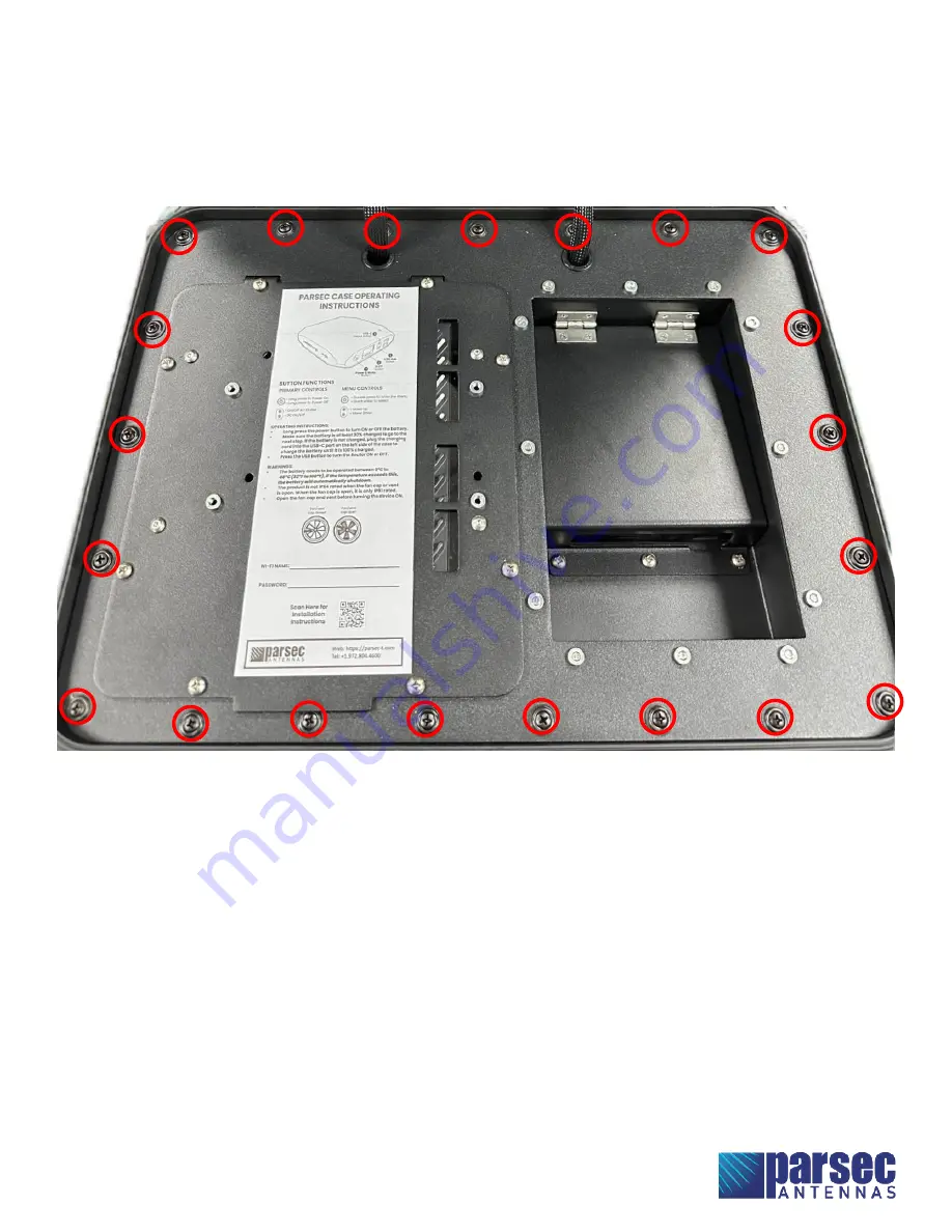
Step 2: Fasten the cover plate to the case. 

A.


Place the cover plate onto the bottom half of the case. 

Ensure that no cables are pinched between 

the cover plate and the case.


B.


Fasten the cover plate to the case using the twenty-one PTA0351 black oval head screws with 
washers provided in the kit, as shown in Figure 12. 


Figure 12: Fasten the cover plate to the case using PTA0351 screws. 


Summary of Contents for BERNESE MOUNTAIN DOG G2

Page 1: ...of 16 Table of Contents Required Tools Accessories 2 Battery and Router Installation 3 Connection 6 Final Assembly 10 Operational Setup 13 Battery Operation and Safety Guidelines 16 BERNESE MOUNTAIN D...

Page 2: ...hers 4 pcs PTA0844 Lock Washers 4 pcs PTA0408 Nuts 4 pcs Ethernet Cords 4 pcs USB C to Barrel Cord PTA0479 Barrel to 4 Pin Cord Battery Tray for OmniCharge 20K Battery Pack Router Plate for Cradlepoin...

Page 3: ...tery tray and secure the Battery Tray Step 2 Mount the router to the cover plate A Remove the Router Plate from the Cover Plate Assembly as shown in Figure 3 to be able to easily install the router to...

Page 4: ...Bernese Mountain Dog G2 Page 4 of 16 Figure 3 Remove the Router Plate from the Cover Plate Figure 4 Remove the film from the Display Covers on the Router Plate...

Page 5: ...Bernese Mountain Dog G2 Page 5 of 16 Figure 5 Mount the R1900 Router to the Router Plate...

Page 6: ...Bernese Mountain Dog G2 Installation Instructions Page 6 of 16 Connection Figure 6 Connection Diagram for Bernese Mountain Dog G2...

Page 7: ...nals B Connect the antenna cables to the designated terminals on the router as shown in the tables and images below Cradlepoint R1900 Antenna Cable Router Terminal CELL 1 MAIN CELL 2 DIV CELL 3 MIMO1...

Page 8: ...ure 8 Figure 8 Omnicharge 20k Battery Pack Connections Right Side Step 3 Connect the fan to the router A Plug the fan power cord into the USB A port on the router shown in Figure 7 Step 4 Connect the...

Page 9: ...the ethernet cords from the router to the RJ 45 ports on the case C Connect the provided ethernet cord to the WAN port on the router shown in Figure 7 D Connect the other end of the ethernet cord from...

Page 10: ...es are properly connected A Inspect every cable connection and ensure that no connections are loose B Use cable ties or other wire management to neatly bundle the cables as shown below Note Ensure tha...

Page 11: ...the bottom half of the case Ensure that no cables are pinched between the cover plate and the case B Fasten the cover plate to the case using the twenty one PTA0351 black oval head screws with washers...

Page 12: ...e and battery cover to the cover plate A Fasten the router plate and battery cover to the cover plate using the eleven PTA0399 TL screws provided in the kit as shown in Figure 13 Figure 13 Fasten the...

Page 13: ...14 Open the fan and vent caps Step 2 Power on the antenna A Turn the battery pack ON by pressing and holding the power button for 3 seconds The display on the battery pack will indicate the battery p...

Page 14: ...s on the router Step 4 Login to Cradlepoint NetCloud A Open a web browser on the computer and type 192 168 0 1 into the address bar This will bring up the Cradlepoint NetCloud login shown in Figure 15...

Page 15: ...RNET and then CONNECTIONS B In the Device List table select the option with a cellular SIM as shown in Figure 17 Figure 17 Select the device with a cellular SIM in Cradlepoint NetCloud Antenna setup i...

Page 16: ...high temperature environment the unit will automatically shut OFF E Keep out of reach of children F The product may become uncomfortable warm reaching 100 F 40 C under extended high power usage While...

Page 17: ...24 inches of the antenna Install the antenna or mast assembly on a windy day Install the mast close to power lines as it can cause serious injuries or death WARNING This document gives detailed instr...

Reviews: