background image

INSTRUCTION REF: IN208             
ISSUE No.  1  
DATE 19.07.11 


Page 14 of 59 


Parry Group Limited, Town End Road, Draycott, Derby, England DE72 

3PT 

www.parry.co.uk 

Hanging the canopy on a wall 

 
The method chosen to hang the canopy to a wall or ceiling will depend greatly on 
the type and material of the wall or ceiling. It is the responsibility of the installer to 
check the structure is strong enough for the weight of the canopy and to use 
appropriate fixings. 
 
If a canopy has been supplied on a stand or mounted to a table it may still need 
to be tied to a wall or ceiling for rigidity. 
 

1.


Choose a suitable position for your unit taking into consideration ducting, 
the location of units underneath it, and current standards. Do not butt the 
unit up against another unit which will get hot. Do not let the position of the 
unit blank off any ventilation vents on any other adjacent units. 


2.


Remove all protective film and packing material. 


3.

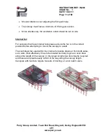
  Holes can be drilled through the back or top of the canopy to screw 

directly to a wall or ceiling. 

In some circumstances it may be beneficial to 

run a baton along the wall for the unit to sit onto, as well as screwing 
directly into the wall. 


4.

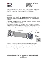
  If in the case of a condensate canopy the unit may be suspended from the 

ceiling with chain. Take steps to prevent the canopy from swaying, which 
could happen as doors into the room are opened and closed.


5.


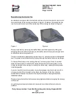
Please note that on each canopy a fat collection tray may be situated to 
one side of the unit, and on condensate canopies a drain valve is located 
in one corner.  To help the liquid flow into the drain or tray, it is best to fix 
the unit at a slight angle. 


Summary of Contents for GT1010

Page 1: ...of 59 Parry Group Limited Town End Road Draycott Derby England DE72 3PT www parry co uk GUIDELINE FOR THE SELECTION INSTALLATION AND OPERATION OF PARRY EXTRACTION CANOPIES MODELS SNACK TYPE CANOPY RA...

Page 2: ...tioning internal fan External fan Hanging on a wall Speed controllers Maintenance instructions Filters Filter specifications External Canopy Value pack External value pack specification Duct mounted f...

Page 3: ...Limited Town End Road Draycott Derby England DE72 3PT www parry co uk Gas Interlock Gas interlock system Interlock controller Pressure switch Gas Solenoid valve and pressure transducer Speed controll...

Page 4: ...e bends The canopies are manufactured from high quality stainless steel and contain a bank of baffle filters that are easily removed for cleaning All canopies are available with the added option of ei...

Page 5: ...uty kitchens Canopy Codes Dimensions A x B x C Weight GT1010 1000 x 1000 x 600 32Kg GT1210 1200 x 1000 x 600 36Kg GT1510 1500 x 1000 x 600 45Kg GT1810 1800 x 1000 x 600 65Kg GT2110 2100 x 1000 x 600 7...

Page 6: ...py and fixing holes to allow one canopy to be bolted to another Simply state when placing your order that you require the canopies to be joined together in a single run General Type Canopy The diagram...

Page 7: ...alth and safety To help decide which size and type of canopy you require for your installation there are a number of standards and recommendation documents available The Heating and Ventilating Contra...

Page 8: ...w it The standard DW 172 states that Unless restricted by walls the plan dimensions of the canopy will always exceed the plan dimensions of the catering equipment by a minimum of 250mm on each free si...

Page 9: ...fitted with a sealed moulded plug must be fitted by a qualified electrician in accordance with current regulations To prevent shocks all appliances whether gas or electric must be earthed To avoid sc...

Page 10: ...py Lights are sold separately Remember that a canopy is flexible and must be handled carefully Each construction site is different and fixings must be designed to suit each installation The preferred...

Page 11: ...al fan For canopies that have internal fans please ensure the fan is in the correct position before attempting to mount the canopy to a wall The centrifugal fan used within the internal fan packs draw...

Page 12: ...is bolted to a plate with a square hole in it using four pieces of threaded bar The plate is then bolted to the canopy through the same holes as the flange To block off the holes in the canopy that a...

Page 13: ...a duct mount fan sized to the length of canopy a pair of flanges and a speed controller Canopies with external fans give the installer greater flexibility as to where the ducting can be mounted Usuall...

Page 14: ...ot butt the unit up against another unit which will get hot Do not let the position of the unit blank off any ventilation vents on any other adjacent units 2 Remove all protective film and packing mat...

Page 15: ...kitchen manager should ensure that the internal sections of the canopy are inspected regularly and cleaned to prevent a build up of grease which could start a fire Filters MUST be washed regularly For...

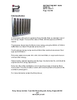
Page 16: ...0mm baffle filters is a total of 50 pascals across the unit The Snack type canopy range use the 400mm filter and the General and Titan type use the 500mm Parry also supply as a spare 430 x 430 mm mesh...

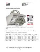
Page 17: ...ucting with two 90 degree bends The fans are rated to an IP rating of IP54 Dust and splashes Canopy Length Single Phase Filters 400 mm Filters 500 mm Fan Spec Flow m sec Rating kW Controller Pair flan...

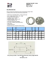
Page 18: ...perating range 40 C to 70 C Thermal protection TK Galv steel casing with flanges Corrosion resistant paint pebble Grey Inlet guard IP54 terminal box Maintenance free sealed for life bearings Single Ph...

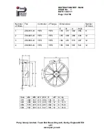
Page 19: ...ontroller 2 Flange Dimensions Number of holes E B A PCD 1 ZSC315 41 YES YES 135 317 382 356 8 2 ZSC400 41 YES YES 155 400 466 438 12 3 ZSC450 41 YES YES 160 451 515 487 12 4 ZSC500 41 YES YES 165 503...

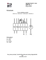
Page 20: ...07 11 Page 20 of 59 Parry Group Limited Town End Road Draycott Derby England DE72 3PT www parry co uk Wiring diagram For the following models ZSC315 41 ZSC400 41 ZSC450 41 ZSC500 41 Wiring Colours U1...

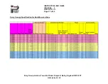
Page 21: ...INSTRUCTION REF IN208 ISSUE No 1 DATE 19 07 11 Page 21 of 59 Parry Group Limited Town End Road Draycott Derby England DE72 3PT www parry co uk Parry Canopy Specification for Duct Mounted Fans...

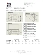
Page 22: ...to hole centre C Minimum distance from edge to hole centre D Maximum cut out diameter E Minimum distance from edge to hole centre F Minimum distance from edge to hole centre G Maximum cut out diamete...

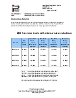
Page 23: ...ultant Resultant Resultant Fan Noise Noise Noise Noise Fan ref Noise Level Level Level Level Level with 1D ST with 1D POD with 2D ST with 2D POD Silencer Silencer Silencer Silencer ZSC315 41 46 dBA 39...

Page 24: ...ll be fixed to the centre of the top panel if it has two or more fans they will be evenly spread along the length of the top panel If another position is required for the mounting of the fan this is p...

Page 25: ...Page 25 of 59 TELEPHONE SERVICE 44 01332 875665 FAX SERVICE 44 01332 875536 Parry Group Limited Town End Road Draycott Derby England DE72 3PT www parry co uk Internal Fans Sizes Fan A B C D E DD 7 7 3...

Page 26: ...1 DATE 2 01 08 Page 26 of 59 TELEPHONE SERVICE 44 01332 875665 FAX SERVICE 44 01332 875536 Parry Group Limited Town End Road Draycott Derby England DE72 3PT www parry co uk Parry Canopy Specification...

Page 27: ...STRUCTION REF IN176 ISSUE No 1 DATE 2 01 08 Page 27 of 59 TELEPHONE SERVICE 44 01332 875665 FAX SERVICE 44 01332 875536 Parry Group Limited Town End Road Draycott Derby England DE72 3PT www parry co u...

Page 28: ...STRUCTION REF IN176 ISSUE No 1 DATE 2 01 08 Page 28 of 59 TELEPHONE SERVICE 44 01332 875665 FAX SERVICE 44 01332 875536 Parry Group Limited Town End Road Draycott Derby England DE72 3PT www parry co u...

Page 29: ...STRUCTION REF IN176 ISSUE No 1 DATE 2 01 08 Page 29 of 59 TELEPHONE SERVICE 44 01332 875665 FAX SERVICE 44 01332 875536 Parry Group Limited Town End Road Draycott Derby England DE72 3PT www parry co u...

Page 30: ...STRUCTION REF IN176 ISSUE No 1 DATE 2 01 08 Page 30 of 59 TELEPHONE SERVICE 44 01332 875665 FAX SERVICE 44 01332 875536 Parry Group Limited Town End Road Draycott Derby England DE72 3PT www parry co u...

Page 31: ...STRUCTION REF IN176 ISSUE No 1 DATE 2 01 08 Page 31 of 59 TELEPHONE SERVICE 44 01332 875665 FAX SERVICE 44 01332 875536 Parry Group Limited Town End Road Draycott Derby England DE72 3PT www parry co u...

Page 32: ...STRUCTION REF IN176 ISSUE No 1 DATE 2 01 08 Page 32 of 59 TELEPHONE SERVICE 44 01332 875665 FAX SERVICE 44 01332 875536 Parry Group Limited Town End Road Draycott Derby England DE72 3PT www parry co u...

Page 33: ...achieved with propeller axial or centrifugal fan loads where absorbed power at full load corresponds to at least 90 of the motor s capacity SPECIFICATION The SC1 is housed in a plastic enclosure rate...

Page 34: ...RICIAN ELECTROMAGNETIC COMPATIBILITY AND GUARANTEE Controls are fitted with integral filters and conform to the requirements of the EEC Directive 89 336 EEC and are CE marked accordingly Testing of un...

Page 35: ...through the knock out holes at the bottom of the unit and ensure electrical connections are correct 4 Switch on the mains supply Switch on the speed controller 5 Rotate the control knob from an anti...

Page 36: ...for speed control by this method Control is best achieved with propeller axial or centrifugal fan loads where absorbed power at full load corresponds to at least 90 of the motor s capacity SPECIFICAT...

Page 37: ...C Directive 89 336 EEC and are CE marked accordingly Testing of the units was conducted against the standard for Adjustable Speed Electrical Power Drive Systems EN 6 1800 3 1997 unrestricted incorpora...

Page 38: ...1 DATE 2 01 08 Page 38 of 59 TELEPHONE SERVICE 44 01332 875665 FAX SERVICE 44 01332 875536 Parry Group Limited Town End Road Draycott Derby England DE72 3PT www parry co uk PCB LAYOUT WIRING THE MOTO...

Page 39: ...ed by IEE Regulations CONTROLS 1 On Off Switch This isolates the motor from the live line Live remains present on the fuse and neutral remains present on the PCB unless a separate isolator is fitted b...

Page 40: ...dstart The control applies full power to the load for a few seconds before dropping back to minimum 6 Rotate speed control knob fully clockwise and check that the fan accelerates to full speed 7 Minim...

Page 41: ...165mm wide x 75mm deep SLB1000 1020mm length x 165mm wide x 75mm deep SLB1300 1320mm length x 165mm wide x 75mm deep DLB700 720mm length x 290mm wide x 75mm deep DLB1000 1020mm length x 290mm wide x 7...

Page 42: ...ght Box There are fixing holes on the light box body that can be easily marked through and drilled to fasten to the underside of the top of the canopy Bulk Head Light Box Fixing holes can be drilled t...

Page 43: ...pliances if the ventilation fans are not operating or if the air flow is below a minimum level The solenoid valve will also shut if the system senses a gas leak anywhere along the pipe work or gas app...

Page 44: ...d Control Panel Pressure Transmitter and Fan Pressure Switch Constant monitoring for low gas pressure Isolation of the gas if the ventilation fan fails Simple installation and commissioning no complex...

Page 45: ...ellow Gas on Red Test fail Yellow Low gas supply Yellow Emergency Stop Yellow Fan Status Yellow Dimensions 128mm Width x 179mm Height x 59mm Depth Contents 1 x Provengas Cooksafe control panel 1 x pre...

Page 46: ...ressure transmitter to the Control Valve output use the Control valve Test point tapping if available There are no pre drilled holes in the Cooksafe enclosure for the input output cable glands as thes...

Page 47: ...Fill time as set above and then flash at 1 sec intervals for the duration of the Prove time If at the end of this time the pressure in the outlet pipe work is sufficient then the red Gas on indicator...

Page 48: ...the event of damages due to the non observance of these instructions improper operation or use of the switch for purposes for which it is not intended the warranty becomes null and void We shall not b...

Page 49: ...w parry co uk Screw C was adjusted in the factory and the adjustment fixed with adhesive This adjustment may not be changed Change the switching point with B screw only Adjust upper and lower switchin...

Page 50: ...2 01 08 Page 50 of 59 TELEPHONE SERVICE 44 01332 875665 FAX SERVICE 44 01332 875536 Parry Group Limited Town End Road Draycott Derby England DE72 3PT www parry co uk Fig 3 Recommended installation arr...

Page 51: ...er than the scale Note With the safety cover removed contact with terminals 1 2 and 3 poses a lethal C hazard mains power voltage Adjusting of upper lower switching point Dial B For higher switching p...

Page 52: ...STRUCTION REF IN176 ISSUE No 1 DATE 2 01 08 Page 52 of 59 TELEPHONE SERVICE 44 01332 875665 FAX SERVICE 44 01332 875536 Parry Group Limited Town End Road Draycott Derby England DE72 3PT www parry co u...

Page 53: ...the gas pressure in the pipe work If the pressure is found to be low the system highlights that there could be a gas leak and the electrical power supply is disconnected from the gas solenoid valve ca...

Page 54: ...k knob switch and printing All models have a double pole illuminated on off rocker switch A facility to set the minimum and maximum fan speed is standard 2 or 3 wire control as standard Electronic ste...

Page 55: ...nt ratings available to special order TYPE Max Full Load Current amps Dimensions HxWxD mm Weight Kg Enclosure IP rating Electrical Supply EFSC 1 5 1 50 87 x 147 x 55 0 35 IP51 240V AC 1Ph 50Hz EFSC 3...

Page 56: ...n details Also the miss use alteration or unauthorised repairs of the equipment will invalidate the warranty During the warranty period it is at Parrys discretion to repair or replace the equipment Wa...

Page 57: ...e Setting up of equipment eg dishwasher detergents levelling and setting up of doors on a 6 burner cooker Excessive carbon build up on griddle plates Over use of lava rock on the chargrills recommende...

Page 58: ...ment and human health which could otherwise be caused by inappropriate waste handling of this product A symbol on the product or on the documents accompanying the product indicates that this appliance...

Page 59: ...n You have several options a Take the unit to an approved WEEE scheme company there will be one in your area b Take the unit to an approved waste disposal site many sites are managed by your local aut...

Reviews: