Parr Instrument 4838 Operating Instructions Manual Download Page 10

4838 Reactor Controller

10

Instructions for the 4838 Reactor 
Controller

Caution!

Check that controller settings are set to 

factory defaults before operating for the fi rst 

time. The default settings are listed at the 

back of this manual. 
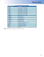
Note:

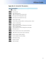
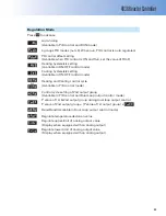
 Controller parameters can be found in 

Appendix A on page 21 of this manual. 

Temperature Control Module

PRIMARY

TEMPERATURE

The 4838 Reactor Controllers have a microprocessor 
based control module that provides full three-term 
PID control with adjustable tuning parameters.  The 
temperature control interface is labeled as Primary 
Temperature
 on front panel.  

To facilitate start up with reasonably good PID con-
trol, parameters for both heating and cooling are 
pre programmed at the factory. 

Output 1 on these controllers drives the heater. Out-
put 2 is not used on the 4838 Controller.  The control 
parameter can be set independently for this output.

Two lines of information, labeled PV and SV, are 
shown on the display during normal operations.  
The upper line (PV) shows the actual temperature 
as read by the control thermocouple.  The lower 
line (SV) shows the set point.  When the controller 
is heating, the Out1 light will illuminate or blink.  
When an alarm condition has been reached, the 
ALM light will illuminate and trip the High Limit 
Reset, cutting power to the heater.

Temperature Control

The easiest way to control temperature with the 
4838 Controller is to use setpoint control.  With set-
point control, the controller will attempt to bring the 
temperature to the value of the setpoint by adjust-
ing the heater output.  

The setpoint may be adjusted by doing the following:

1.  Press the up or down arrow until the lower 

display shows the desired setpoint.  The lower 
display will blink, showing the value has not 
been set yet.

2.  Press the set button.  The lower display will stop 

blinking, showing the new value has been set.

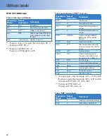
High Temperature Alarm Setpoint

The 4838 Reactor Controller also has a High Tem-
perature Alarm built into it.  When the temperature 
exceeds this limit, it will pop the High Limit Reset, 
preventing power from going to the heater.  The 
High Temperature Alarm setpoint may be adjusted 
by doing the following:

1.  Press the circular arrow key three times.  The up-

per display will read AL1H and the lower display 
will read the High Temperature Alarm setpoint 
(usually 375 °C).  

2.  Use the up or down arrow to adjust this to the 

desired setpoint.

3.  Press the up or down arrow until the lower 

display shows the desired setpoint.  The lower 
display will blink, showing the value has not 
been set yet.

4.  Press the set button.  The lower display will stop 

blinking, showing the new value has been set.

5.  Pressing the set button again will return the dis-

play to the main screen.

PID groups

a.  The primary temperature controller contains 

4 groups of PID parameters (PID0, PID1, PID2 
and PID3), which can be used to store up to four 
different sets of PID parameters. Each group is 
identifi ed by the SV used during the autotuning 
cycle.

b.  The parameter displayed is the group in use 

with exception of PID4. When PID4 is set, the PID 
parameters will automatically switch between 
PID groups 0, 1, 2 and PID group 3, depending 
on which group’s SV best matches the current 
temperature (PV).

Summary of Contents for 4838

Page 1: ...4838 Reactor Controller Operating Instruction Manual...

Page 2: ...ry Switches and Indicators 8 Protective Fuses and Relays 8 High Limit Reset 9 Access to the Controller Cabinet 9 Fuses 9 Instructions for the 4838 Reactor Controller Temperature Control Module 10 Comm...

Page 3: ...h of these controllers and describe the several optional control modules which can be added to these ex pandable units The users should study the instruc tions carefully before using any of these cont...

Page 4: ...4838 Controller There are no user serviceable parts inside the prod uct other than what is speci cally called out and discussed in this manual Advanced troubleshooting instructions beyond the scope of...

Page 5: ...l 4838 Controllers operate with aType J Iron Constantan thermocouple The total resistance of the thermo couple and the lead wires should not exceed 100 ohms If the resistance of the thermocouple circu...

Page 6: ...pera tion within the limits speci ed for that design But in order to preserve the validity of these de signs all temperature and pressure limits must be observed and no attempt should be made to incre...

Page 7: ...troller will not be affected by radiant heat Connections Labeled connections are provided on the rear panel of the controller Heating Only The heating output connector is to be used only with Company...

Page 8: ...When the light comes on the user must nd the source of the problem correct it and then manually reset the system using the high limit reset button on the front of the controller The Main Power Switch...

Page 9: ...imit setting This must be manually reset before heating can occur again On Model 4838 Controllers the high temperature limit is preset at the factory to 375 C for most sys tems On these controllers an...

Page 10: ...the value of the setpoint by adjust ing the heater output The setpoint may be adjusted by doing the following 1 Press the up or down arrow until the lower display shows the desired setpoint The lower...

Page 11: ...p and Soak The 4838 Controller has a programming feature which allows more exibility when compared to set point control Rather than controlling temperature to a single set point a ramp and soak progra...

Page 12: ...set key to solidify the change 11 Press set to return to the main screen Note that the lower display of the main screen has changed to show the program step Note The program will attempt to hold the...

Page 13: ...r knows the expected heat up time It is useful to keep this step 02 separate from step 01 so you can adjust step 01 to match the heat up time The time is zero making this a step function in stead of a...

Page 14: ...involving reactants corrosive to stainless steel the transducer body can be replaced with an isolator of special alloys which will keep the reactants away from the transducer Users should consult wit...

Page 15: ...As an added safety feature there is also a second ary alarm which will trip the High Limit Reset when breached This secondary alarm provides a redun dant high temperature safety cut off which will sh...

Page 16: ...The soft ware is located on the CD at software _ _ _ Com exe 6 Once copied to the PC open the _ _ _ Com exe le No installation is necessary 7 At the main _ _ _ Com program screen select protocol set P...

Page 17: ...se address 3 and an HTM ETLM will use ad dress 4 5 Click the Save button and save a REC le to an appropriate place on the PC When the chart is generated it will write to this le 6 When you return to t...

Page 18: ...Out1 read only Heater output If using a type J or type K thermocouple SP 0 If using an RTD SP 1 Press and hold down SET for 5 sec Operation Mode Select type value Comment InPt J Input type tPUn C Temp...

Page 19: ...ol mode ON OFF MANUAL PID and PID PROG S HC Heat Heat Cool control ALA1 2 Alarm operates when PV value is higher than SV Value ALH setting SALA OFF System alarm CoSH ON Communication write function th...

Page 20: ...nge tP L 0 Lower limit temperature range CTRL ON OFF Control mode ON OFF MANUAL PID and PID PROG S HC Heat Heat Cool control ALA1 6 Alarm operates when PV value is higher than AL1H value SALA OFF Syst...

Page 21: ...ontrol mode Select heating cooling control or dual loop output control Alarm 1 mode setting Alarm 2 mode setting Only available on PrimaryTemperature Controller Alarm 3 mode setting Only available on...

Page 22: ...function is enabled Lower limit alarm 1 This parameter is available only when ALA1 function is enabled Upper limit alarm 2 This parameter is available only when ALA2 function is enabled Lower limit a...

Page 23: ...control mode or Heating and Cooling control cycle Available in PID control mode Control cycle setting of 2nd output group Available in PID control and Dual Loop output control mode P value of 1st 2nd...

Page 24: ...tension wire type J 25 ft A470E6 Thermocouple extension wire type J 30 ft A470E9 Thermocouple extension wire type J 35 ft A470E10 Thermocouple extension wire type J 40 ft A472E4 Thermocouple type J 5...

Page 25: ...s 30 ft covered A1905E10 Pressure harness 35 ft covered A1905E11 Pressure harness 40 ft covered A1906EP02 Transducer 200 psi A1906EP05 Transducer 500 psi A1906EP10 Transducer 1000 psi A1906EP20 Transd...

Page 26: ...ft A470E10 Thermocouple extension wire 40 ft A472E Thermocouple type J 7 1 2 length A472E2 Thermocouple type J 9 1 2 length A472E3 Thermocouple type J 11 1 2 length A472E4 Thermocouple type J 5 1 2 le...

Reviews: