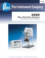
Parr Instrument 4590 Operating Instructions Manual Download Page 5

4590 Micro Reactors

P a r r   I n s t r u m e n t   C o m p a n y

4

PREFACE

Scope

These instructions describe the installation, opera-

tion and maintenance of Parr Series 4590 Bench Top 

Micro Reactors which are offered in three sizes 25, 

50 and 100 mL. They cover the basic steps to be fol-

lowed when installing these reactors and describe 

the function of all standard components. They are 

intended to be used in conjunction with several 

related instruction sheets listed below. This infor-

mation describes several components which are 

common to most Parr pressure reaction equipment, 

and includes safety precautions and other related in-

formation applicable to all reaction laboratories. The 

users should study all of these instructions carefully 

before starting to use these vessels so that they will 

fully understand the capabilities and limitations of 

the equipment.

Related Instructions

The following Parr publications are also included to 

further your understanding of this instrument and 

its component parts:

 No.

Description 

201M

Limited Warranty 

230M

Safety Precautions to be observed when 

operating Pressure Reaction Equipment

231M

Operating Instructions for Parr Safety 

Rupture Discs

234M

Operating and Maintenance Instructions 

for Parr Magnetic Drives

323M

Operating Instructions for Parr Pressure 

Relief Valves

548M

Operating Instructions for 4848 Reactor 

Controllers

FX004

Health & Safety Assurance Certification

Intended Usage

This system has been designed for use as a high 
pressure reactor system. It has been designed, built, 
and tested to strict physical and electrical standards. 
However, it is the user’s responsibility to install and 
operate it in conformance with local pressure and 
electrical codes. 

If this equipment is used in a manner beyond its 
intended usage, the protection provided by the 
equipment may be impaired.

Safety Information

To avoid electrical shock, always:

1.  Use a properly grounded electrical outlet of 

correct voltage and current handling capability.

2.  Ensure that the equipment is connected to 

electrical service according to local national 
electrical codes. Failure to properly connect may 
create a fire or shock hazard.

3.  For continued protection against possible hazard, 

replace fuses with same type and rating of fuse.

4.  Disconnect from the power supply before 

maintenance or servicing.

To avoid personal injury:

1.  Do not use in the presence of flammable or 

combustible materials; fire or explosion may 
result. This device contains components which 
may ignite such material.

2.  Refer servicing to qualified personnel.

General Specifications

Electrical Ratings

Controller ratings are found in the Operating Instruc-
tions for the controller supplied with your reactor 
and on the controller data plate. 

Before connecting a controller to an electrical outlet, 
the user must be certain that the electrical outlet has 
an earth ground connection and that the line, load 
and other characteristics of the installation do not 
exceed the following limits:

Voltage: 

Fluctuations in the line voltage should not 

exceed 10% of the rated nominal voltage shown on 
the data plate.

Frequency: 

Controllers can be operated from either 

a 50 or 60 Hertz power supply without affecting their 
operation or calibration. 

Current: 

The total current drawn should not exceed 

the rating shown on the data plate on the controller 
by more than 10 percent.

Thermocouple: 

Unless otherwise specified, all 

Series 4848 Controllers operate with a Type J (iron-
constantan) thermocouple.  The total resistance of 
the thermocouple and the lead wires should not 
exceed 100 ohms.  If the resistance of the thermo-
couple circuit is higher, it will reduce the sensitivity 
of the control system.

Artisan Technology Group - Quality Instrumentation ... Guaranteed | (888) 88-SOURCE | www.artisantg.com

Summary of Contents for 4590

Page 1: ...s underutilized and idle equipment along with credit for buybacks and trade ins Custom engineering so your equipment works exactly as you specify Critical and expedited services Leasing Rentals Demos...

Page 2: ...399M 4590 Micro BenchTop Reactors Operating Instruction Manual Artisan Technology Group Quality Instrumentation Guaranteed 888 88 SOURCE www artisantg com...

Page 3: ...Artisan Technology Group Quality Instrumentation Guaranteed 888 88 SOURCE www artisantg com...

Page 4: ...USE THE VESSEL 14 To open the Vessel 14 Before Closing the Vessel 14 Sealing Vessels with PTFE Gaskets 14 Sealing with Flexible Graphite Gaskets 14 O Ring Closures 14 Gas Connections 15 Pressurizing...

Page 5: ...e protection provided by the equipment may be impaired Safety Information To avoid electrical shock always 1 Use a properly grounded electrical outlet of correct voltage and current handling capabilit...

Page 6: ...ng carriers The vessel motor heater and tem perature controller may be packed separately for convenience in shipping but these parts are easily reassembled Examine the components closely for any loose...

Page 7: ...nvenient use in daily operation within certain temperature and pres sure limits using gaskets closures and other elements carefully selected for safe operation within the limits specified for that des...

Page 8: ...r Self Sealing O Ring Closure The flat gasket is held in a recess in the vessel head and a machine pilot on the cylinder closes the recess to completely contain the gasket The split ring closure used...

Page 9: ...ture since the strength of any material will normally fall off as the temperature is increased Temperature and pressure limits are also affected by the physical properties and temperature limits of th...

Page 10: ...the heater into the heater socket on the rear panel of the Series 4848 Reactor Controller 4 Plug the motor cord into the motor socket on the rear of the controller Secure the clamp on the motor cord w...

Page 11: ...id Sampling Valve The liquid sampling valve is attached to the same fitting as the gas inlet valve and connected to the same dip tube With this arrangement incoming gas is always introduced below the...

Page 12: ...under 1000 psi a relief valve is added and set to protect the gage A 1000 psi rupture disc is installed as the fail safe vessel protection For highly corrosive applications where the vapor phase might...

Page 13: ...con tinuous runs at high speeds the oiling rate should be increased to three drops per minute If the motor becomes sluggish flush it with a non flammable solvent in a well ventilated area Disconnect...

Page 14: ...Notes w w w p a r r i n s t c o m 13 Artisan Technology Group Quality Instrumentation Guaranteed 888 88 SOURCE www artisantg com...

Page 15: ...flow under the loading pressure Routinely inspect cap screws on the split ring closure for lubrication and cleanliness It is important to clean and lubricate them periodically so that the required to...

Page 16: ...t ting gas so as not to exceed the maximum working limit Remember that any subsequent increase in temperature will raise the pressure Also be sure that the amount of liquid placed in the vessel is car...

Page 17: ...in place on the head before attaching any head fittings The compres sion ring cannot be installed after fittings have been screwed into the head 8 Clean all threads and gas passages thoroughly and re...

Page 18: ...usual occurrence raises any safety questions To return a vessel for repair contact Parr Instrument Company for a return authorization number RMA Apparatus returned for testing and overhaul should be s...

Page 19: ...lit Ring For parts made from alternate materials use the codes shown below as a suffix to the standard part number CM Alloy 400 CC Alloy 20Cb3 CT Alloy 600 CA Titanium G2 or G4 CG Alloy B 2 CH Alloy C...

Page 20: ...haft Impeller Assembly Part No Description Code A1987HC Shaft Impeller 25 50 mL SC A1987HC2 Shaft Impeller 100 mL SC A1987HC3 Shaft Impeller 25 50 mL RV A1987HC4 Shaft Impeller 100 mL RV A1987HC5 Shaf...

Page 21: ...C A451VB VALVE 555VBAD RED ADAPTER 154VB ELBOW A455HC S R ASSEMBLY 420HC2 ADAPTER A451VB VALVE 555VBAD RED ADAPTER 1401HC HEX RED NIPPLE A455VB2 VALVE A1120HC6 MAG DRIVE 836HC GAGE ADAPTER 593HC SERI...

Page 22: ...well 100 mL RV A2067HC5 Thermowell 25 50mL FH A2067HC4 Thermowell 100mL FH Dip Tube Part No Description Code 1443HC DipTube 25 mL 1443HC2 DipTube 50 mL 1443HC3 DipTube 100 mL Shaft Impeller Assembly P...

Page 23: ...C5 A2345HC5 1452HC12 NIPPLE HEX 1 4 NPTM ADAPTER SINGLE VALVE 1 4 NPTM DIP TUBE 50mL 2430HC19 A176VB COMPRESSION NUT SHORT SPLIT RING ASSEMBLY VALVE STRAIGHT A176VB A176VB AND LATCH HP HT ELBOW 1 4NPT...

Page 24: ...Gasket Flexible Graphite SR FG Thermowell Part No Description Code A2067HC5 Thermowell 25 50mL FH A2067HC4 Thermowell 100mL FH Dip Tube Part No Description 1443HC DipTube 25 mL 1443HC2 DipTube 50 mL...

Page 25: ...able Speed XP Explosion Proof Rated TW Thermowell HP HT High Pressure HighTemperature OVERARM PLATE OPTICAL WHEEL ENCASEMENT MOTOR RELEASE KNOB DRIVEN PULLEY BELT HUB ASSEMBLY SNAP RING ISOLATOR UPPER...

Page 26: ...SCREW 2224HC BELT GUARD STD 4 TW19NL LOCK WASHER OPTIONAL 845HC2 RELEASE KNOB 299HC2 BUSHING 328E7 HOLE PLUG A2223HC DRIVEN SHAFT ASSY 863HC COLLAR 2075HC2 COUPLING SN5013HX HEX NUT OPTIONAL A2262E T...

Page 27: ...7NL 2209HC BEARING 2187HC COUPLING FLEXIBLE SNAP RING 3 8 LOCK WASHER 4X SB1932BT06 10 32 X 3 8 BHSCS 2222HC DRIVE SHAFT 4X TW19NL LOCK WASHER 2226HC A3443HC BEARING HOUSING ASSEMBLY REF 2221HC HP VOL...

Page 28: ...4590MicroReactors w w w p a r r i n s t c o m 27 4593 Micro Reactor with Fixed Head Artisan Technology Group Quality Instrumentation Guaranteed 888 88 SOURCE www artisantg com...

Page 29: ...399M R06 01 22 15 Artisan Technology Group Quality Instrumentation Guaranteed 888 88 SOURCE www artisantg com...

Page 30: ...uipment Have surplus equipment taking up shelf space We ll give it a new home Learn more Visit us at artisantg com for more info on price quotes drivers technical specifications manuals and documentat...

Reviews: