background image

- 10 -

4560 Mini Bench Top Reactors

Parr Instrument Company

Revision 6-28-02

HOW TO USE THE VESSEL

Removable Head Vessel

Flat Gasket Closure

Always remove vessels from the

support stand before attempting to open or
close them.

                                                             
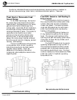
To Open the Vessel

Open the gas release valve to

discharge any internal pressure; then loosen
the six cap screws in the split ring sections.
Loosen the cone pointed screw in the outer
band and lower the band to rest on the
table.  The ring sections can now be
removed, and the head with all attached
fittings is free to be lifted from the cylinder.
Handle the head carefully so as not to
damage the stirring shaft and other internals
when they are outside of the cylinder.

                                                             
Before Closing the Vessel

Examine the head gasket carefully to

be sure that it is in good condition.  After
considerable use the PTFE gaskets may
extrude a thin, ragged edge around the
inside and outside diameters.  This does not
necessarily mean that the gasket must be
replaced, but the extruded portion should be
removed with a sharp knife.  Examine the
mating surfaces on the cylinder and the
head to be sure they are clean and free from
burrs then set the head on the cylinder.

                                                             
To Close the Vessel

Slide the two ring sections into place

and position them so that the shallow socket
drilled in the outer surface of one of the ring
sections is 180

!

 from the gage face. Raise

the outer band into place around the ring
sections and position the band so that the
cone pointed screw enters the socket
described above; then tighten the screw
lightly to hold the band in place.

Fixed Head Vessels

Fixed head vessels are opened and

closed with the same procedure used for
removable vessels except that they are
opened and closed with the head in place.
Before opening the vessel lower the heater
and swing it well to the side so that it will not
be damaged by any materials that drip from
the vessel as it is opened.  When closing the
vessel always hold the cylinder until both
split ring sections and the drop band are in
place to lock the cylinder to the head.

                                                             
Sealing Vessels with PTFE Gaskets

Tighten each of the cap screws with

the wrench furnished with the apparatus.
Apply a firm but hard pull to each screw.  If a
torque wrench is available, apply 25 ft-lbs to
each screw.  Tightening should proceed in a
criss-cross pattern rather than progressively
around the circle.  Let the vessel stand for
about five minutes after the initial tightening;
then tighten the cap screws again.  This will
compensate for any tendency of the PTFE
gasket to flow under the loading pressure.

Routinely inspect cap screws on split

ring closure for lubrication and cleanliness.
It is important to lubricate periodically so that
the required torque is achieved when
tightening the bolts.

                                                             
O-Ring Closures

The split rings used with the self

sealing O-ring do not include the six cap
screws used to seal the flat gaskets.  The O-
ring is held in a groove on the underside of
the head.  Before closing the vessel
examine this O-ring carefully to see that it is
in good condition.  Slide the head and
cylinder together until the top of the cylinder
and the bottom of the head come together.
Now install the two split ring sections and
lock them together with the drop band.

Summary of Contents for 4560

Page 1: ...Parr Instrument Company No 396M Operating Instruction Manual for 4560 Mini Bench Top Reactors...

Page 2: ...losion Proof Operation 14 Periodic Pressure Tests 15 Accessories 15 Liners 15 Spare Parts Kits 15 General Maintenance Notes 16 Parts List 17 Standard Internal Parts List 17 Reaction Vessel Parts List...

Page 3: ...bility for the selection of pressure equipment the prospective user is often faced with a choice between over or under designed equipment The hazards introduced by under designed pressure vessels are...

Page 4: ...ort system Flat PTFE Gasket or Self Sealing O Ring Closure The flat gasket is held in a recess in the vessel head and a machine pilot on the cylinder closes the recess to completely contain the gasket...

Page 5: ...iderably if used at temperatures above 300 C For better service in the 300 C to 350 C operating range Parr recommends a flexible graphite gasket No 457HC3KL The maximum working pressure and temperatur...

Page 6: ...rea where the split ring rests The thumb screw on the drop band which encircles the split ring closure should fit into the slot on this bracket This will keep the vessel from rotating when stirring vi...

Page 7: ...turned on Similarly a short vessel must never be heated in a deep mantle Without full contact with a metal wall a mantle will overheat and burn out The smaller 100 and 160 mL Mini Reactors are heated...

Page 8: ...rom this valve will be drawn from the top of the reactor Liquid Sampling Valve The liquid sampling valve is attached to the same fitting as the gas inlet valve and connected to the same dip tube This...

Page 9: ...hich would be released if the rupture disc should burst A connector for attaching 1 4 OD tubing to the discharge port of the rupture disc is provided for this purpose Type J Thermocouple A Type J Ther...

Page 10: ...ighten the screw lightly to hold the band in place Fixed Head Vessels Fixed head vessels are opened and closed with the same procedure used for removable vessels except that they are opened and closed...

Page 11: ...out of the vessel and into the gas tank when the inlet valve is opened If there is any possibility that the tank pressure might not be high enough to force gas into the reactor install a one way check...

Page 12: ...made with only water to check the apparatus before starting the first experimental runs For this initial test fill the cylinder not more than half full of water and run the temperature up to 150 C wh...

Page 13: ...with SAE 10 motor oil and adjust the oiler to feed one drop per minute into the air stream For long continuous runs at high speeds the oiling rate should be increased to three drops per minute If the...

Page 14: ...park hazard associated with these units can be resolved by installing the controller in a remote location outside of the hazardous area or by enclosing it in an approved explosion proof housing If enc...

Page 15: ...ped prepaid to the Parr Instrument Company 211 53rd Street Moline Illinois 61265 An order or letter of instructions should be mailed to the same address as no repair work will be started without speci...

Page 16: ...roughly and remove all tape fragments when overhauling a vessel An ultrasonic bath is excellent for cleaning metal parts but do not place a thermocouple probe pressure gage face seals or ball bearings...

Page 17: ...s Parr Instrument Company Revision 6 28 02 Bomb Closure and Standard Internal Parts 232HCF 454HC 457HC2 A456HC A455HC 818HC_ A834HC or 914HC 452HC_ A837HC_ 822HC_ 832HC_ 456HCF2 232HCF A834HC_ or A92H...

Page 18: ...RVFG 2201HC Head for thermocouple FHFG 2201HC2 Head for thermowell FHFG 2201HC5 Head for FMD FHFG 2201HC6 Head for FMD FHFG 2340HC Head for thermocouple RVOR 2340HC2 Head for thermowell RVOR 2340HC5 H...

Page 19: ...C Impeller with screw for 822HC series shafts Gaskets Seals 457HC2 Head Gasket PTFE FG 457HC3KL Head Gasket Flexible Graphite FG 2341HCJV O ring FKM OR 2341HCJK O ring FFKM OR 48HC Gasket silver A1120...

Page 20: ...ounded 300mL Type J A833HC Male connector 1 8 NPT M X 1 8T for thermocouple A138CA Male Connector 1 8NPT M X 1 4T for thermowell A472E2 Thermocouple Grounded 450mL Type J A472E3 Thermocouple Grounded...

Page 21: ...g 841HC Snap Ring External 693 842HC Snap Ring 1 804 858HC2 Pulley Driven 862HC Support Hub 299HC2 Bushing PTFE Upper Drive Shafts A2223HC Upper Drive Shaft Part No Description Shaft Couplings 2075HC...

Page 22: ...22 4560 Mini Bench Top Reactors Parr Instrument Company Revision 6 28 02 Bomb Support Stand with Fixed Head and 1 8 hp Stirrer Drive Motor...

Page 23: ...23 4560 Mini Bench Top Reactors Parr Instrument Company Revision 6 28 02 Bomb Support Stand with Moveable Vessel and 1 4 hp Stirrer Drive Motor...

Page 24: ...h Top Reactors Parr Instrument Company Revision 6 28 02 PARR INSTRUMENT COMPANY 211 Fifty third Street Moline Illinois 61265 USA 309 762 7716 800 872 7720 Fax 309 762 9453 http www parrinst com E Mail...

Reviews: