


70
GB
MT
Operation
Caution! Risk of injury!
- Ensure that you have suficient
space in which to work and that
you do not endanger other peo-
ple.
- All hoods and protective devices
must be assembled properly be-
fore commissioning.
- Disconnect the mains plug be-
fore changing the setting on the
device.
Setting up
Place the bench drill on a solid surface.
Ideally, bolt the drill to the surface. Use the
four holes in the baseplate (17) for this.
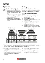
Selecting the speed
1. Release the locking bolt (11) on the
gear cover (3).
2. Open the gear cover (3).
3. Release the retaining screw (12) on the
motor unit (13).
4. Using the lever (33), slide the motor
unit (13) forwards a little to release the
load on the V-belts (29).
5. Place the V-belts (29) on the desired
assembly to reach the speciied speed:
A
B
C
D
I
II
III
Spindle-side drive
pulley (
30)
Motor side drive
pulley (
31)
Pos.
speed
[1/min]
Pos.
speed
[1/min]
Pos.
speed
[1/min]
1.
D - I
500
4.
D - III
830
7.
B - III
1600
2.
D - II
680
5.
B - I
980
8.
A - II
2000
3.
C - I
770
6.
C - II
1100
9.
A - III
2500
The gear cover (3) is equipped with a interlock switch (32). If the gear cover (3) is
not closed correctly, the device cannot be switched on.
6. Using the lever (33), slide the motor
unit (13) backwards to re-tighten the V-
belts (29).
7. The V-belts (29) are correctly tensioned
when they give way slightly when
pressed.
8. Re-tighten the retaining screw (12) on
the motor unit (13).
9. Close the gear cover (3). Fasten the
locking bolt (11) on the gear cover .
Summary of Contents for PTBM 500 E5
Page 4: ...4 6 7 4 28 D 13 14 27 25 27 C...
Page 97: ...97...
Page 104: ...104...
Page 105: ...105 E 33 31 30 32 3 11 29 13 12 33...
Page 106: ...106 3 38 39 40 37 36 36 G H I 36 41 13 9 F 34 35...
Page 107: ...107...


