Parkside PKZS 2000 A1 Operating Manual Download Page 27

22

GB

8.11 Using the laser (Fig. 3/19/20)

• 

To switch on:

 Move the ON/OFF switch of the laser (34) 

to the “1” position. A laser line is projected onto the mate-
rial you wish to process, providing an exact guide for the 
cut.

• 

To switch off:

 Move the ON/OFF switch of the laser (34) 

to the “0” position.

8.12 Adjusting the laser (Fig. 20)

If the laser (33) ceases to indicate the correct cutting line, 
you  can  readjust  the  laser.  To  do  so,  open  the  screws  (e) 
and set the laser by moving sideways to that the laser beam 
strikes the teeth of the saw blade (6).

9.  Transport

• Tighten the set screw (26) in order to lock the rotary table 

(14)

• Activate the release lever (3), press the machine head (4) 

downwards and secure with the safety pin (23). The saw is 
now locked in its bottom position.

• Fix the saw’s drag function with the locking screw for drag 

guide (20) in rear position.

• Carry the equipment by th

e fi

xed saw table (15).

• When reassembling the equipment proceed as described 

under section 7.

10. Maintenance

m


Warning!

 Prior to any adjustment, maintenance or ser-

vice work disconnect the mains power plug!

General maintenance measures

Wipe chips and dust off the machine from time to time using 
a cloth. In order to extend the service life of the tool, oil the 
rotary parts once monthly. Do not oil the motor.
When cleaning the plastic do not use corrosive products.

Brush inspection

Check the carbon brushes after the 

fi

rst 50 operating hours 

with a new machine, or when new brushes have been 

fi

tted. 

After carrying out the 

fi

rst check, repeat the check every 10 

operating hours.
If the carbon is worn to a length of 6 mm,  or if the spring 
or contact wire are burned or damaged,  it is necessary to 
replace both brushes. If the brushes are found to be usable 
following removal, it is possible to reinstall them.

When servicing the carbon brushes, open the two latches 
counterclockwise (as shown in Figure 21). Then remove the 
carbon brushes.
Replace the carbon brushes in the reverse order.

11. Storage

Store the device and its accessories in a dark, dry and frost-
proof place that is inaccessible to children. The optimum stor-
age temperature is between 5 and 30˚C. 
Store the electrical tool in its original packaging.
Cover the electrical tool in order to protect it from dust and 
moisture.

• Use the handle (1) to tilt the machine head (4) to the left 

until it coincides with the required angle value (in this con-
nection see also section 8.6).

• Re- tighten th

e fi

xing screw (22).

• Cut as described under section 8.3.

8.8 Limiting the cutting depth (Fig. 3/14)

• The cutting depth can be in

fi

nitely adjusted using the screw 

(24). To do this loosen the knurled nut on the screw (24). 
Move the stop for the cutting depth limitre (25) to the out-
side. Turn the screw (24) in or out to set the required cutting 
depth. Then re- tighten the knurled nut on the screw (24).

• Check the setting by completing a test cut.

8.9 Sawdust bag (Fig. 1/22)

The saw is equipped with a debris bag (17) for sawdust and 
chips.
Squeeze together the metal ring on the dust bag and attach 
it to the outlet opening in the motor area.
The debris bag (17) can be emptied by means of a zipper 
at the bottom.

8.10 Changing the saw blade (Fig. 1/2/15-18) 
Remove the power plug!
Important!
Wear  safety  gloves  when  changing  the  saw  blade. 
Risk of injury!

• Swing the machine head (4) upwards and lock with the 

safety pin (23).

• Press the release lever (3). Swing up the saw blade guard 

(5) to the point where the recess in the saw blade guard 
(5) is above th

e fl

ange bolt (29).

• With one hand insert the allen key (d) in the 

fl

ange bolt 

(29).

• Hold  the  Allen  key  (d)  and  slowly  close  the  saw  blade 

guard (5) until it touches the Allen key (d).

• Firmly  press  the  saw  shaft  lock  (31)  and  slowly  rotate 

the 

fl

ange  bolt  (29)  in  clockwise  direction.  The  saw 

shaft lock (31) engages after no more than one rotation. 
Attention! When loosening the screw, the machine head 
lowers slightly.

• Now, using a little more force, slacken the 

fl

ange bolt (29) 

in the clockwise direction.

• Turn the 

fl

ange screw (29) right out and remove the exter-

na

l fl

ange (30).

• Take the blade (6) off the inner 

fl

ange (32) and pull out 

downwards.

• Carefully clean the 

fl

ange screw (29),  outer 

fl

ange (30) 

and inner 

fl

ange (32).

• Fit and fasten the new saw blade (6) in reverse order.
• Important! The cutting angle of the teeth,  in other words 

the direction of rotation of the saw blade (6) must coincide 
with the direction of the arrow on the housing.

• Before continuing your work make sure that all safety de-

vices are in good working condition.

• Important! Every time that you change the saw blade (6), 

check to see that it spins freely in the table insert (10) in 
both perpendicular and 45° angle settings.

• Important! The work to change and align the saw blade 

(6) must be carried out correctly.

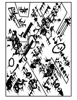
Summary of Contents for PKZS 2000 A1

Page 1: ... 2000 A1 AT DE CH AT KAPP ZUG UND GEHRUNGSSÄGE PKZS 2000 A1 Bedienungs und Sicherheitshinweise Originalbetriebsanleitung DE SLIDING CROSS CUT MITRE SAW PKZS 2000 A1 Operating and Safety Instructions Translation of Original Operating Manual GB ...

Page 2: ...tructions Page 14 Klappen Sie vor dem Lesen die Seite mit den Abbildungen aus und machen Sie sich anschließend mit allen Funktionen des Gerätes vertraut DE AT CH Before reading unfold the page containing the illustrations and familiarise yourself with all functions of the device GB ...

Page 3: ...2 4 1 18 19 20 21 22 23 26 3 7a 5 8 15 9 1 2 3 4 5 6 8 9 10 11 33 25 24 12 13 14 16a 15 16 16b 7 17 ...

Page 4: ...10 11 6 7 12 13 22 27 c c 28 d 22 14 25 24 9 8 16a 16b e 8 16a 16b 23 1 2 7 14 13 4 3 4 16 7 15 14 18 14 a 6 19 6 b 14 4 4 7 7 14 14 ...

Page 5: ...16 17 18 19 34 15 20 33 e e 21 22 17 5 35 31 32 6 30 29 d ...

Page 6: ...ferumfang 3 4 Bestimmungsgemäße Verwendung 4 5 Wichtige Hinweise 4 6 Technische Daten 7 7 Vor Inbetriebnahme 7 8 Aufbau und Bedienung 8 9 Transport 10 10 Wartung 10 11 Lagerung 10 12 Elektrischer Anschluss 10 13 Entsorgung und Wiederverwertung 11 14 Störungsabhilfe 12 15 Garantieurkunde 13 ...

Page 7: ...achten DE AT CH Schutzbrille tragen DE AT CH Achtung Verletzungsgefahr Nicht in das laufende Sägeblatt greifen DE AT CH Achtung Laserstrahlung DE AT CH Schutzklasse II Doppelisolierung DE AT CH Gehörschutz tragen DE AT CH Bei Staubentwicklung Atemschutz tragen Erklärung der Symbole auf dem Gerät ...

Page 8: ... arbeiten die im Ge brauch des Gerätes unterwiesen und über die damit verbun denen Gefahren unterrichtet sind Das geforderte Mindest alter ist einzuhalten Neben den in dieser Bedienungsanleitung enthaltenen Si cherheitshinweisen und den besonderen Vorschriften Ih res Landes sind die für den Betrieb von baugleichen Maschinen allgemein anerkannten technischen Regeln zu beachten Wir übernehmen keine ...

Page 9: ...metallteilen des Sägeblattes Gehörschäden bei Nichtverwendung des nötigen Gehör schutzes Gesundheitsschädliche Emissionen von Holzstäuben bei Verwendung in geschlossenen Räumen Bitte beachten Sie dass unsere Geräte bestimmungsgemäß nicht für den gewerblichen handwerklichen oder indust riellen Einsatz konstruiert wurden Wir übernehmen keine Gewährleistung wenn das Gerät in Gewerbe Handwerks oder In...

Page 10: ...usgewählt wird Tragen Sie eine geeignete persönliche Schutzausrüs tung Dies schließt ein 9 Benutzen Sie Schutzausrüstung Tragen Sie eine Schutzbrille Verwenden Sie bei stauberzeugenden Arbeiten eine Atemmaske 10 Schließen Sie die Staubabsaug Einrichtung an Falls Anschlüsse zur Staubabsaugung und Auffang einrichtung vorhanden sind überzeugen Sie sich dass diese angeschlossen und richtig benutzt wer...

Page 11: ...Be wahren Sie diese am besten in der Originalverpackung oder speziellen Behältnissen auf Tragen Sie Schutz handschuhe um die Griffsicherheit zu verbessern und das Verletzungsrisiko weiter zu mindern Gehörschutz zur Verminderung des Risikos schwer hörig zu werden Atemschutz zur Verminderung des Risikos gefährli chen Staub einzuatmen Tragen Sie beim Hantieren mit Sägeblättern und rauen Werkstoffen H...

Page 12: ...heitsvorrichtungen ordnungsgemäß montiert sein Das Sägeblatt muss frei laufen können Bei bereits bearbeitetem Holz auf Fremdkörper wie z B Nägel oder Schrauben usw achten Bevor Sie den Ein Ausschalter betätigen vergewissern Sie sich ob das Sägeblatt richtig montiert ist und bewegli che Teile leichtgängig sind 10 Stellen Sie vor der Benutzung von Einsatzwerkzeugen sicher dass alle Schutzvorrichtung...

Page 13: ...h 14 auf den ge wünschten Winkel einstellen Der Zeiger 12 auf dem Drehtisch muss mit dem gewünschtem Winkelmaß der Skala 13 auf dem feststehenden Sägetisch 15 überein stimmen Überzeugen Sie sich vor dem Anschließen der Maschine dass die Daten auf dem Typenschild mit den Netzdaten übereinstimmen 8 Aufbau und Bedienung 8 1 Zug Kapp und Gehrungssäge aufbauen Abb 1 2 3 4 5 Zum Verstellen des Drehtisch...

Page 14: ...schließen bis dieser am Innensechs kantschlüssel d ansteht Die Feststellschraube 26 wieder festziehen um Drehtisch 14 zu fixieren Schnitt wie unter Punkt 8 3 beschrieben ausführen 8 5 Feinjustierung des Anschlags für Gehrungsschnitt 45 Abb 1 6 10 11 Anschlagwinkel nicht im Lieferumfang enthalten Den Maschinenkopf 4 nach unten senken und mit dem Sicherungsbolzen 23 fixieren Den Drehtisch 14 auf 0 S...

Page 15: ...zulässig ist Das Gerät kann bei ungünstigen Netzverhältnissen zu vo rübergehenden Spannungsschwankungen führen Sägewellensperre 31 fest drücken und Flanschschrau be 29 langsam im Uhrzeigersinn drehen Nach max einer Umdrehung rastet die Sägewellensperre 31 ein Achtung Beim Lösen der Schraube senkt sich der Maschi nenkopf leicht Jetzt mit etwas mehr Kraftaufwand Flanschschraube 29 im Uhrzeigersinn l...

Page 16: ...Ihrer Müllab fuhr Das Produkt ist ausschließlich zur Verwendung an An schlußpunkten vorgesehen die a eine maximale zulässige Netzimpedanz Z Zmax 0 382 Ω nicht überschreiten oder b eine Dauerstrombelastbarkeit des Netzes von mindes tens 100 A je Phase haben Sie müssen als Benutzer sicherstellen wenn nötig in Rück sprache mit Ihrem Energieversorgungsunternehmen daß Ihr Anschlußpunkt an dem Sie das P...

Page 17: ...n Netzanlage überlastet Lampen andere Motoren etc Verwenden Sie keine andere Geräte oder Motoren auf demselben Stromkreis Motor überhitzt sich leicht Überlastung des Motors ungenügende Kühlung des Motors Überlastung des Motors beim Schneiden verhindern Staub vom Motor entfernen damit eine optimale Küh lung des Motors gewährleistet ist Sägeschnitt ist rau oder gewellt Sägeblatt stumpf Zahnform nich...

Page 18: ...deinwirkungen wie z B Schäden durch Herunterfallen sowie durch verwendungsgemäßen üblichen Verschleiß ausgeschlossen Der Garantieanspruch erlischt wenn an dem Gerät bereits Eingriffe vorgenommen wurden Die Garantiezeit beträgt 3 Jahre und beginnt mit dem Kaufdatum des Gerätes Garantieansprüche sind vor Ablauf der Garantie zeit innerhalb von zwei Wochen nachdem Sie den Defekt erkannt haben geltend ...

Page 19: ... delivery 16 4 Intended use 17 5 Safety information 17 6 Technical data 19 7 Before starting the equipment 20 8 Attachment and operation 20 9 Transport 22 10 Maintenance 22 11 Storage 22 12 Electrical connection 23 13 Disposal and recycling 23 14 Troubleshooting 24 15 Warranty certificate 25 ...

Page 20: ...ons and safety instructions GB Wear safety goggles GB Important Risk of injury Never reach into the running saw blade GB Important Laser radiation GB Protection Class II double shielded GB Wear ear muffs GB Wear a breathing mask Explanation of the symbols on the equipment ...

Page 21: ...fully follow its information The machine can only be operated by persons who were instructed concerning the operation of the machine and who are informed about the associated dangers The minimum age requirement must be complied with In addition to the safety instructions contained in this oper ating manual and the specific regulations of your country the technical rules generally accepted for the ...

Page 22: ... electric tools for protection against electric shock and the risk of injury and fire Read all these notices before using the electric tool and keep the safety in structions for later reference Safe work 1 Keep the work area orderly Disorder in the work area can lead to accidents 2 Take environmental influences into account Do not expose electric tools to rain Do not use electric tools in a damp o...

Page 23: ...ons in which a sudden slip could cause one or both hands to come into con tact with the saw blade 14 Take care of your tools Keep cutting tools sharp and clean in order to be able to work better and more safely Follow the instructions for lubrication and for tool re placement Check the connection cable of the electric tool regu larly and have it replaced by a recognised specialist when damaged Che...

Page 24: ...ound the machine must be level clean and free of loose particles such as chips and cutting residues Only use saw blades for which the maximum permis sible speed is not lower than the maximum spindle speed of the machine and which are suitable for the material to be cut Be sure to only use spacers and spindle rings speci fied by the manufacturer as suitable for the intended purpose Attention Do not...

Page 25: ... blade 6 is no more than 8 mm Before making the cut check that no collision could occur between the stop rail 16a and the saw blade 6 Tighten the set screw 16b again Move the machine head 4 to its upper position The work piece must have a minimum height of 3mm and a minimum width of 10 mm Make sure that the workpiece is always secured with the clamping device Noise Total noise values determined in...

Page 26: ... the rotary table 14 to the de sired angle refer also to point 8 4 in this regard Re tighten the set screw 26 in order to secure the rotary table Undo the locking screw 22 Use the handle 1 to push back the machine head 4 and fix it in this position if required dependent on the cutting width Place the piece of wood to be cut at the stop rail 16 and on the turntable 14 Lock the material with the cla...

Page 27: ...d moisture Use the handle 1 to tilt the machine head 4 to the left until it coincides with the required angle value in this con nection see also section 8 6 Re tighten the fixing screw 22 Cut as described under section 8 3 8 8 Limiting the cutting depth Fig 3 14 The cutting depth can be infinitely adjusted using the screw 24 To do this loosen the knurled nut on the screw 24 Move the stop for the c...

Page 28: ...nection complies with the appli cable VDE and DIN provisions The customer s mains connection as well as the exten sion cable used must also comply with these regula tions The product meets the requirements of EN 61000 3 11 and is subject to special connection conditions This means that use of the product at any freely selectable connection point is not allowed Given unfavorable conditions in the p...

Page 29: ...rk are overloaded lamps other motors etc Do not use any other equipment or motors on the same circuit Motor overheats easily Overloading of the motor insufficient cooling of the motor Avoid overloading the motor while cutting remove dust from the motor in order to ensure optimal cooling of the motor Saw cut is rough or wavy Saw blade dull tooth shape not appropriate for the material thickness Resh...

Page 30: ...xternal influences e g damage caused by the device being dropped and normal wear resulting from proper operation of the device The guarantee is rendered null and void if any attempt is made to tamper with the device The guarantee is valid for a period of 3 years starting from the purchase date of the device Guarantee claims should be submit ted before the end of the guarantee period within two wee...

Page 31: ...26 ...

Page 32: ...e následující shodu podle smernice EU a norem pro výrobek SK prehlasuje nasledujúcu zhodu podla smernice EU a noriem pre výrobok HR ovime izjavljuje da postoji sukladnost prema EU smjernica i normama za sljedece artikle RS potvrđuje sledeću usklađenost prema smernicama EZ i normama za artikal RO declară următoarea conformitate corespunzător directivelor şi normelor UE pentru articolul BG декларира...

Page 33: ......

Page 34: ......

Page 35: ......

Page 36: ...Stand der Informationen Last Information Update Update 03 2018 Ident No 302388_3901207974 SCHEPPACH FABRIKATION VON HOLZBEARBEITUNGSMASCHINEN GMBH Günzburger Str 69 D 89335 Ichenhausen IAN 302388 1 ...

Reviews: