


PDWS 125 A1
■
24
│
GB
│
IE
Attaching the grinding disc
CAUTION!
►
Disconnect the compressed air tool from
the compressed air supply before replacing
the accessory tool or accessories, or before
carrying out adjustments or servicing. The
spindle must be at a standstill.
Lock the spindle
♦
Place the rear clamping flange on the spindle
. This is correctly attached if the spindle
cannot be rotated.
♦
Place the open-ended spanner supplied
over the collar of the rear clamping flange to
prevent it from turning.
Attaching the grinding disc
♦
Place the grinding disc on the rear clamping
flange .
The grinding disc must be evenly placed on
the rear clamping flange .
Fixing/loosening the front flange
The 2 sides of the front flange are different.
Screw the front flange onto the spindle as
follows:
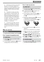
For thin grinding discs (see figure 1):
♦
The collar on the front flange faces upwards
so that the thin grinding disc can be safely
clamped.
12
≤ 3,2 mm
fig. 1
For thick grinding discs (see figure 2):
> 3,2 mm
fig. 2
The collar on the front flange faces downwards
so that the front flange can be safely attached
to the spindle .
♦
Locking the spindle .
♦
Tighten the front flange in a clockwise direc-
tion using the two-hole spanner .
Loosening the front flange:
♦
Lock the spindle .
♦
Undo the front flange in an anticlockwise
direction using the two-hole spanner .
Fitting the connector nipple
♦
Remove the plastic protective cap from the
appliance‘s air inlet.
♦
Wrap the threads on the connector nipple
with the teflon tape supplied.
♦
Screw the connector nipple into the air inlet.
Summary of Contents for PDWS 125 A1
Page 3: ......


