ASSEMBLY
Read and follow the assembly and adjustment instructions.
Do not discard any parts or materials until the unit is as-
sembled.
NOTE:
Torque is measured in foot-pounds (metric unit is
Nm). This measurement describes how tight a nut or bolt
must be. The torque is measured with a torque wrench.
WARNING
Always wear ANSI compliant safety glasses or eye
shields while assembling the trimmer.
The following components will be found in parts bag with
quantities in ( ):
(1)Field Trimmer Operator’s Manual
(1)Engine Operator’s Manual
(1)500 ml Bottle of Oil
(1)T-Handle Wrench
(4)0.155 in. Trimmer Lines (4 lines make 2 sets)
WARNING
Before doing any assembly or maintenance to the unit,
remove the wire from the spark plug.
TOOLS REQUIRED
(1)Utility Knife to Cut Carton
(1)Oil Funnel
(1)Torque Wrench to Check Fastener Tightness
(1)T-Handle Wrench (included in parts bag)
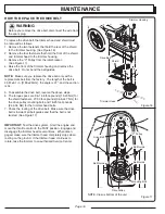
ADJUST THE HANDLE
1. Hold the handle with one hand and loosen both handle
adjustment knobs until the ratchet teeth are disengaged.
Do not remove the handle adjustment knobs.
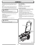
(See Figure 2)
2. Press sides of handle apart and rotate the handle to
the desired position behind the trimmer.
3. Stand in the operator’s position behind the trimmer to
make sure handle is adjusted to a comfortable position
4. Tighten the handle adjustment knobs to 13-15 foot-pounds
[18-20 Nm].
5. To attach the recoil start handle to the rope guide, twist the
rope through the rope guide mounted on the right side of
the handle.
Page 7
Figure 2
Handle
Recoil Start
Handle
Rope Guide
Handle Pivot
Handle
Adjustment
Knob


