in
Parking and access control equipment manufactured in the UK
Bi-Folding Speed Gate
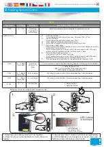
M12 Bolt
4 No.
(Centre Stop)
Reset
OUTPUT
ON
ON
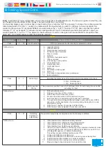
DIP
1 2 3 4 5 6 7 8
PRES
PULSE
FILT
ASB
SENS
FREQ
Loop Detector External
(Optional)
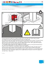
1.
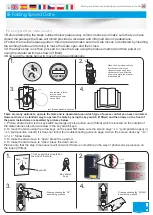
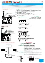
You need to prepare the ground to accept the bi-fold tower. The drawings are a brief guide and for dimensions you should
ONLY
consult issued CAD drawings. Be sure to CAT scan any area before excavation!
2.
The gate to will be installed in 2 steps if it is “cast-in”, If you have opted for a “bolt-down” installation then you would create
the same plinth and if level install the towers on this. After the correct hole is dug according to CAD drawings issued you will
then move to step 3 for the first pour of (C40) grade concrete.
3.
As per picture if in an area with a high water table you need to ensure you have adequate drainage. “D” shows the first pour
of concrete (mentioned above) this should be 700mm deep. When this has cured you drill and chem fix 4 20mm threaded bars
into the surface to line up with the fixing holes in the gate tower base plate, (these have a nut above and below the tower base
plate for adjustment/alignment purposes).
4.
The gate leaf & tower will be closeed (base plate first) onto the threaded bar. here it will secured and levelled up in all
direction ensuring that the tower sits up out of the hole to the correct (level) height. This is a very important step as when the
other gate is fitted. It will need to line up with the first fitted leaf. Please note that this is very important as there is only a
MINIMAL adjustment once the gates receive the second pour of concrete.
Now move on to step 5
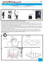
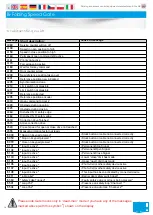
The numbers in the text document below relate to the drawings below.
3.
1.
2.
4.
3h 45 mins
60 5
10
15
20
25
30
35
40
45
50
55
Loop Detector Internal
(Optional)
A
A
=1400mm
B
C
B
=1300mm
=1300mm
C
TST FUZ-PF
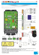
Control Panel
*Brake
Release tool
*2 Items above located on rear
of middle tower door
D
E
Master/Slave module
TSTRUFZ-COM
*Manual Winding
Handle
5
Component Identification

