Parker VRD355 Series Installation Manual Download Page 32

32

IA VRD UK.INDD RH 02.06

Digital Power Amplifier

Series VRD350 and VRD355

Installation Manual

Parker Hannifin GmbH & Co. KG

Hydraulic Controls Division

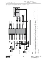
The comparator used to generate a COMMAND 
SIGNAL  REACHED  (“IN  POSITION“)  signal. 
Simple (actual value) checks can thus be performed 
(e.g.  clamping  pressure  monitoring). The  control 
difference U12 is compared with the defined win-
dow in the comparator. The comparator signal is 
output accordingly depending on the result of the 
comparison.
A set comparator (within the window) is indicated 
by a slowly flashing LED “RESET RAMP”. If the 
“Reset  Ramp”  signal  is  also  present,  the  LED 
flashes quickly.

Comparator Function with E2 = 2

The comparator is used to generate a switching 
threshold for the control. The actual value U11 is 
compared directly with the values defined in P21 
and P22. If U11 exceeds the comparative value, 
the  control  is  switched  on.  One  condition,  how-
ever, is that a signal is also present at the “Reset 
Ramp“ input.

3.14. Serial Interface

Remote  operation  or  remote  setting  of  param-
eters  can  be  carried  out  by  means  of  the  serial 
interface. The  following  transmission  parameters 
are applicable:

Assignment of the Serial Interface

Parameter  changes  via  the  serial  in-
terface  should  only  be  carried  out  by 
trained  personnel. The  drive  must  be 
stopped during parameter changes. We 

recommend switching the card’s enable off.

Connection to the PC is via a so-called null mo-
dem cable.
The  program  PROVRD350/355  (Order  No.  HR 
59.500 010) is available to carry out programming 
and  remote  control. This  permits  simple  remote 
control  and  programming  of  the  amplifier  cards 
via  a  PC.  On  one  hand  this  facilitates  program-
ming and increases the clarity, and on the other 
it opens up the possibility of a convenient storage 
and  documentation  of  parameter  configurations. 
The program can also be used to adapt the basic 
settings (default settings) (see also page 14) to the 
user’s specific circumstances.

3.15. ABG35S

The plug-in control panel ABG35S can easily be 
attached to amplifier cards of the VRD355 range 
for displaying and changing parameters and values. 
Afterwards, it can be removed, thus disabling unau-
thorized access to the cards. It provides the same 
keys and 7-segment display as the front panel of 
the VRD350. Further, the same test sockets are 
incorporated for commissioning and servicing.
As an additional feature, the ABG35S enables the 
storage of one complete parameter set on-board. 
By this means, the settings can be copied from one 
amplifier to an unlimited number of others in a very 
short  time.  No  further  components  are  required 
(see also page 23).

The data record in the ABG35S must 
correspond  to  the  software  version  of 
the amplifier.

Only  the  PROVRD  versions V4.0  and 
later  may  be  used  for  amplifier  cards 
with  software  release V2.0  and  later. 
PROVRD  version V4.0  can  be  used 

with older software versions (as of V1.04) of the 
amplifier cards.

Transmission rate

9600 Baud

Data format

8 data-bits, 1 stop-bit, parity none

Voltage level

5V

Summary of Contents for VRD355 Series

Page 1: ...ision Gutenbergstr 38 41564 Kaarst Germany Tel 49 181 99 44 43 0 Fax 49 2131 513 230 E mail infohcd parker com Copyright 2003 Parker Hanni n GmbH Co KG Bulletin HY11 AL287 M1 UK Installation Manual Se...

Page 2: ...lectoruseanyproductorsystem it is important that you analyse all aspects of your application and review the information concerning the product or system in the current product catalogue Due to the var...

Page 3: ...n Generators 24 3 3 Offset 25 3 4 Valve Curve Linearisation 25 3 5 Adjustment of Current Gain 25 3 6 Dither 25 3 7 Current Controller 25 3 8 Output Stages 25 3 9 Step Functions 26 3 10 Control Circuit...

Page 4: ...Simple operation by 4 entry keys and 3 digit LED display Fault indication by numeric code Variable dither amplitude and frequency Gain for solenoids A and B can be set indepen dantly Different valve c...

Page 5: ...0 10 150kOhm Digital 0 V 0 1 1 V 3 30 Outputs Ext supply voltage V 24 10 ripple 5 Reference V 10 10 10mA Analogue V 0 10 5mA Digital mA 50 Solenoids A 0 8 2 7 3 5 Interfaces Serial RS 232C Adjustment...

Page 6: ...enoids or position indicator with 7 5V null voltage Code Ext closed loop 0 without 0 0 10V 1 4 20mA 2 0 20mA Code Sensor assignment 01 controlled 12 Flow valves NG6 22 Directional valves NG6 32 Direct...

Page 7: ...ence The following devices are to be regarded as strong sources of interference Switching power supply units Frequency converters Drive modules Mains lters with wiring even if screened AC DC commutato...

Page 8: ...ke a potential equalisation Use only cables with a Cu screening grid and a covering of 85 whenever possible Avoid screening lms The screen may not be interrupted along the entire length of the cable I...

Page 9: ...Digital Power Ampli er Series VRD350 and VRD355 Installation Manual 9 IA VRD UK INDD RH 02 06 Parker Hanni n GmbH Co KG Hydraulic Controls Division 1 4 Block Diagram Entire System...

Page 10: ...RD UK INDD RH 02 06 Digital Power Ampli er Series VRD350 and VRD355 Installation Manual Parker Hanni n GmbH Co KG Hydraulic Controls Division Feedback Option hardware only with boards for closed loop...

Page 11: ...7 5V Voltage input without terminating resistance Used for potentiometric transmitter systems in which the loop current is limited to smal values Linearity of the transmitter signal is maintained Cur...

Page 12: ...le emergency stop measures must be taken Application Construction and Operation of ABG35S The ABG35S plug in control unit is used in con junction with the VRD355 proportional ampli er It can easily be...

Page 13: ...anni n GmbH Co KG Hydraulic Controls Division 2 2 Programming Programming Instructions for U S P and E Values Select mode U1 S1 P1 or E1 can be selected Select address Display contents e g S2 has the...

Page 14: ...he ampli er This setting depends on the type of ampli er see also type code This basic setting can be recovered from memory by pressing the 4 keys at the same time up to 10 seconds after the supply vo...

Page 15: ...Hydraulic Controls Division 2 3 Block Diagram Open Loop Control Software functions Open loop Parameter functions U parameter display of internal measured values S parameter internal command signals an...

Page 16: ...Hydraulic Controls Division Closed Loop only with boards for closed loop systems Closed loop Parameter functions U parameter display of internal measured values S parameter internal command signals an...

Page 17: ...systems External closed loop Parameter functions U parameter display of internal measured values S parameter internal command signals and ramps H parameter auxiliary parameters P parameter operating...

Page 18: ...vision Remote Loop Control only with boards for closed loop systems Remote loop control external closed loop E2 2 Parameter functions U parameter display of internal measured values S parameter intern...

Page 19: ...lic Controls Division Bypass Controller only with boards for closed loop systems Bypass controller Parameter functions U parameter display of internal measured values S parameter internal command sign...

Page 20: ...cting variable Note Parameter setting and diagnostics only possible for VRD355 using ABG35S Only trained staff should make pa rameter changes The drive should be switched off whilst adjusting para met...

Page 21: ...3 03 V of 0 30 a setpoint of 3 V corresponds to 30 see also page 25 section 3 6 P6 Dither frequency variable in steps from 0 to 647 Hz steps 0 16 40 60 80 110 130 160 220 327 647 in Hz See also page...

Page 22: ...trol only with boards for closed loop systems not active 0 active 1 remote loop control 2 bypass control 3 safety function active only with E14 1 4 E3 Solenoid type 3 5A 9V solenoid coil 1 8 1 reserve...

Page 23: ...data in ABG35S S Load data to ampli er L E16 Activates action selected with E15 Proceeding Press button E The display shows the function selec tedpreviously with parameter E15 S or L Activate the data...

Page 24: ...al Command Signal 5 and Command Signal 6 SW5 and SW6 The command signal inputs 5 and 6 are de signed for signals 0 10 V These setpoints are also passed through the ramp function generator ramp if E8 1...

Page 25: ...dither signal reduces the hysteresis of spool movement Generally low frequency signals are more effective however they may result in noticeable disturbances noise oscil lations Values between 80Hz for...

Page 26: ...or selections 1 to 6 U13 can be positive or negative depending on the difference between feedback and set value Then either solenoid A or B is energized 3 11 To set Zero Point General Case Place the f...

Page 27: ...KP P share of the PID controller P15 has no function E14 0 set Parameter P14 can be used to program a T portion delayingtimefunctionelement Effect on P16 The integral portion is determined by P17 whi...

Page 28: ...E g in position control loops the ramps determine the speed of the drive Using the equations given on page 22 enables the computation of parameters from the loop gain factor In cases where these calc...

Page 29: ...pressure sensors we recom mend that great care be taken The zero volt wiring screening and PE connection are critical Faults in the signal can lead to a triggering of the wire break monitor Instabili...

Page 30: ...s preferably used If the actual value now exceeds this comparative value the control switches on Even if the actual value is under the switching threshold the control remains active The signal at the...

Page 31: ...P21 and P22 Setting E2 3 activates the bypass P13 deter mines the gain of the bypass loop P15 is without any function and P16 sets the P portion P17 the I Portion and P18 the D Portion of the PID con...

Page 32: ...s via a so called null mo dem cable The program PROVRD350 355 Order No HR 59 500 010 is available to carry out programming and remote control This permits simple remote control and programming of the...

Page 33: ...e gure page 9 4 3 Malfunction and Error Messages The current in the output stages is monitored in the ampli er If the total current exceeds a speci c limit an electronic cut out responds and switches...

Page 34: ...10V output PE decoupled 10V output 22 Solenoid A Solenoid A Solenoid A 24 Solenoid B Solenoid B Solenoid B 26 Supply 0V Supply 0V Analogue 0 28 Solenoid A Solenoid A Solenoid A 30 Solenoid B Solenoid...

Page 35: ...eshold P15 0 255 P17 I portion 0 255 P18 D portion 0 255 P19 T portion of DT1 element 0 255 P20 Gain for feedback signal 0 00 2 00 P21 Window Set feedback 0 V 0 00 9 99 P22 Window Set feedback 0 V 0 0...

Page 36: ...Setting Basic Version VRD35X 031 00 old new S1 S4 0 S5 S8 0 H1 H2 Set to 0 after commissioning P1 0 00 P2 0 P3 1 00 P4 1 00 P5 0 80 P6 110Hz P7 0 00 P8 0 00 P9 P10 0 00 P11 1 P12 1 P13 0 P14 0 P15 9...

Page 37: ...open loop version Note All screens are to be earthed over a large areal Earth ampli er with short lines Bridge unused analogue inputs to analogue 0V In the case of terminal names with a number of lett...

Page 38: ...areal Earth ampli er with short lines Bridge unused analogue inputs to analogue 0V In the case of terminal names with a number of letters the terminals are bridged on the ampli er If no electrical iso...

Page 39: ...real Earth ampli er with short lines Bridge unused analogue inputs to analogue 0V In the case of terminal names with a number of letters the terminals are bridged on the ampli er If no electrical isol...

Page 40: ...eal Earth ampli er with short lines Bridge unused analogue inputs to analogue 0V In the case of terminal names with a number of letters the terminals are bridged on the ampli er If no electrical isola...

Page 41: ...e areal Earth ampli er with short lines Bridge unused analogue inputs to analogue 0V In the case of terminal names with a number of letters the terminals are bridged on the ampli er If no electrical i...

Page 42: ...areal Earth ampli er with short lines Bridge unused analogue inputs to analogue 0V In the case of terminal names with a number of letters the terminals are bridged on the ampli er If no electrical is...

Page 43: ...rge areal Earth ampli er with short lines Bridge unused analogue inputs to analogue 0V In the case of terminal names with a number of letters the terminals are bridged on the ampli er If no electrical...

Page 44: ...44 IA VRD UK INDD RH 02 06 Digital Power Ampli er Series VRD350 and VRD355 Installation Manual Parker Hanni n GmbH Co KG Hydraulic Controls Division...

Reviews: