Digital Power Amplifier
Series VRD350 and VRD355
Installation Manual
29
IA VRD UK.INDD RH 02.06
Parker Hannifin GmbH & Co. KG
Hydraulic Controls Division
The internal command signal used for
this purpose serves as a final value
(position value). The drive is run to this
value according to the pre-set ramp.
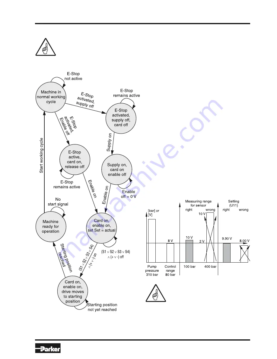
Status Chart of Safety Function
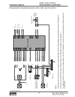
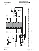
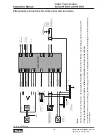
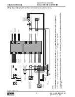
External Control, Pressure Control
Pressure sensors can be designed in two or
three-wire technology. The sensor signal is either
a voltage from 0...10V or a current from 0...20mA
or 4...20mA. The parameter E11 should be set
between 7 and 9. Apart from an adjustment to the
sensor signal, this also prevents controller param-
eters U13 < 0 (see page 22). Wire break monitoring
is only possible with 4...20mA sensor signals.
When connecting pressure sensors we recom-
mend that great care be taken. The zero volt wiring,
screening and PE connection are critical. Faults
in the signal can lead to a triggering of the wire
break monitor. Instabilities in the control loop are
also possible.
The scaling of the sensor signal is very important
for a high quality pressure control. This also guar-
antees a maximum exploitation of the resolution.
The maximum pressure to be controlled is decisive.
The closer the sensor signal is to 10V or 20mA,
the more favourable this is. In other words, the
measuring range of the sensor must be adapted to
the pressure range of the application. Furthermore,
the setting of the actual value adjustment must also
be given special attention. At the maximum pres-
sure to be controlled, almost 9.90V should appear
in display U11.
Example:
When setting the zero point, care must
be taken because pressure valves do
not permit a drop in pressure to 0 bar
on account of their design.


