


42
VIX AE SERVO DRIVE USER GUIDE
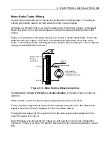
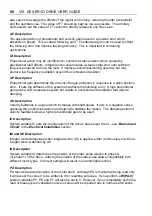
Encoder Input/Outputs
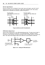
Figure 3-20 shows the circuit details of the encoder inputs and outputs, note the /Z and Z
outputs use the same circuit configuration. With resolver feedback on X2, the encoder
outputs at X4 is simulated at a resolution of 4096 counts per rev.
Encoder inputs
using 26LS32 quad differential
line receiver
Encoder outputs
using 26LS31 quad differential
line driver
drive
inputs
X4
X4
drive
outputs
Figure 3-20. Encoder I/O Circuit Details
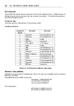
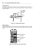
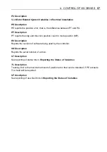
Differential Analogue Input
Control of the ViX base drive is via a differential analogue input. The input circuit, shown in
Figure 3-21, can interface to an ex/-10V differential signal. Analogue to digital
conversion (12-bit resolution) converts the analogue input to a digital value for use within the
drive. The value of the analogue input can be read as a count via system variable AI.
+
-
ANA1-
ANA1+
Input
impedance
200K
Drive
AI, analogue
input expressed
as a count
Software offset controlled
by system variable AO
A to D
Note: both inputs must
be connected - cannot
be used as a single ended
input
0V
GND
Figure 3-21. Analogue Differential Input
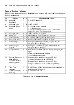
Summary of Contents for ViX250AE
Page 2: ......
Page 57: ...50 VIX AE SERVO DRIVE USER GUIDE...
Page 123: ...116 VIX AE SERVO DRIVE USER GUIDE...
Page 135: ......


