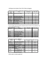
3. Setting menu description of item F0~F5 of factory debugging:
F 0
: NTSC system geometry adjustment (No adjustment can be made for the PAL system)
Screen
display
Notes
Initial value
Max. value
NT.H.PHASE
60Hz line center setting
15
31
NT.V.POSI
60Hz field center setting
5
15
NT.V.SISE
60Hz field amplitude setting
20
63
NT.V.LIN
60Hz linearity setting
15
31
NT.V.SC
60Hz field S correction
15
31
NT.HBOW
Bow correction
4
07
NT.HPARA
Parallelogram correction
4
07
H.BLK.LEFT
Line left black
0
07
H.BLK.RIGHT
Line right black
0
07
F 1:
PAL system geometry adjustment (deviation relative to NTSC value) (adjustment can
only be made under PAL signal)
Screen display
Notes
Initial value
Max. value
H.PHASE
50Hz line center setting
0
-11~10
V.POS
50Hz field center setting
0
-11~10
V.SIZE
50Hz field amplitude setting
0
-11~10
V.LIN
50Hz linearity setting
0
-11~10
V.SC
50Hz
field S correction
0
-11~10
HBOW
Bow correction
4
-8~07
HPARA
Parallelogram correction
4
-8~07
F2: N system correction adjustment
Display
Notes
Recommended
value
Max. value
N.H.WID
Horizontal width adjustment
54
0~63
N.PARABOLA
Parabola adjustment
58
0~127
N.TRAPEZIUM Trapezium correction
20
0~63
N.TOP.CORNER Top
corner
linearity
adjustment.
15
0~31
N.BTM.CORNER Bottom corner linearity
adjustment.
17
0~31
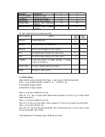
N.V.EHT
Field amplitude high voltage
regulation adjustment
3
0~7
N.H.EHT
Line amplitude high voltage
regulation adjustment
3
0~7
F3:PAL
system correction adjustment


