Parker TGSS 740 User Manual Download Page 11

True Ground Speed Sensor (TGSS) 740


11 


Installation


4.1.3.


Mounting the TGSS to a vehicle 

It is up to the original equipment manufacturer (OEM) to ensure the product is 
securely mounted to the vehicle. 

The following guidelines are related to physically attaching the TGSS to the 
mounting bracket on a vehicle: 


The TGSS should be secured with 

bolts in all 3 bolt holes

 using 6 mm 

Hex Head


bolts and locking washers. 

The bolts should be tightened to 5.4-7.3 Nm (48-65 in lbs). 

Appropriate length bolts are routed from the underside of the unit through the 
mounting plate and tightened into the shock absorbers on the unit's base. The bolts 
should engage the threads in the shock absorbers to a maximum depth of 6.35 mm 
(¼"). 


4.1.4.


Line of sight clearance 

It is important for the sight line of the radar beam to be as unobstructed as possible. 
Interference with radar beam can lead to false or erratic speed readings. 

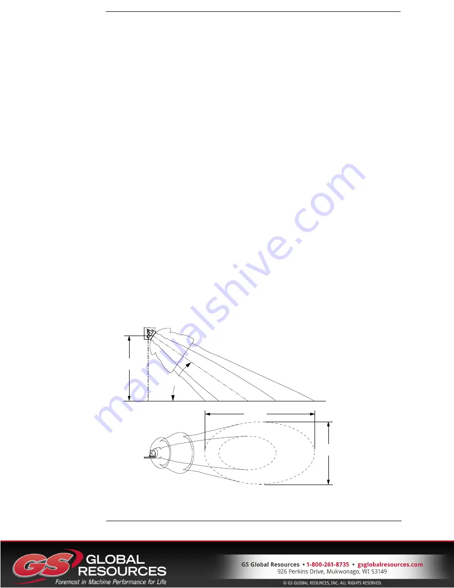
The radar beam pattern is shown in Figure 5: Doppler line of sight. The smaller 
region is the -3dB level and the larger region is the -10 dB level. These areas are the 
relative sensitivity of the TGSS to motion.  

The-3dB region is the area where the TGSS is most sensitive. This path must be clear 
of any objects. Interference in this area will have a high likelihood of degrading the 
performance of the product's ability to provide accurate speed measurement.  

The larger -10dB region is a lower sensitivity area. Objects that interfere in this area 
have a potential to be an issue.  


35°

1000

959

1697


Figure 6: Doppler line of sight 

Summary of Contents for TGSS 740

Page 1: ...TGSS True Ground Speed Sensor TGSS 740 User Manual HY33 5005 IB US Ed 01 2012 UM TGSS 740000 00 201201 03...

Page 2: ...ough its own analysis and testing is solely responsible for making the final selection of the system and components and assuring that all performance endurance maintenance safety and warning requireme...

Page 3: ...tion 9 4 1 Installation Guidelines 9 4 1 1 Mounting Bracket 9 4 1 2 Mounting Angle 10 4 1 3 Mounting the TGSS to a vehicle 11 4 1 4 Line of sight clearance 11 4 1 5 Installation Validation 12 4 2 Perf...

Page 4: ...rked with a warning symbol in the left margin indicate that a hazardous situation exists If precautions are not taken this could result in death serious injury or major property damage CAUTION Section...

Page 5: ...not be used If the control system shows error functions or if electronic modules cabling or connectors are damaged the system shall not be used WARNING Electronic control systems in an inappropriate...

Page 6: ...ls which can interfere with the functions of the system 2 1 3 Safety during start up WARNING The machine s engine must not be started before the control system is mounted and its electrical functions...

Page 7: ...sensor When the target terrain is moving relative to the sensor there is a change in the frequency of the reflected signal Doppler shift The ground speed is calculated by measuring the change in freq...

Page 8: ...tif 1 le dispositif ne doit pas causer d interf rence radio lectrique et 2 le dispositif doit tre en mesure d accepter toute interf rence radio lectrique m me si celle ci est susceptible de compromett...

Page 9: ...4 1 Installation Guidelines The TGSS 740 Radar measures motion relative to itself It is important to prevent unwanted motion in order to achieve optimal performance The unwanted motion could be of the...

Page 10: ...e the effect of machine vibration The vibration mounts have an internal M6 thread the recommended installation torque is 5 4 7 3 Nm 48 65 in lbs 4 1 2 Mounting Angle Any error in the mounting angle wi...

Page 11: ...he shock absorbers to a maximum depth of 6 35 mm 4 1 4 Line of sight clearance It is important for the sight line of the radar beam to be as unobstructed as possible Interference with radar beam can l...

Page 12: ...face most of the signal is reflected away from the radar 4 1 5 1 Line of sight evaluation With the vehicle stationary over a smooth surface slowly sweep the engine rpm over it s range Monitor the TGSS...

Page 13: ...return signal strength There is no return signal over standing water Short term loss of signal from small puddles is handled by the software When driving over large areas of water the output speed may...

Page 14: ...35 mounting angle The equation for Doppler shift frequency fd is given by V target velocity mph fo transceiver frequency Hz c speed of light 671 x 106 mph where angle between beam and path of target...

Page 15: ...nnector Pin out Pin Function 1 Output Speed square wave 2 Battery 9 to 16 Vdc 3 Ground When the unit is equipped with the Radar present output the connector is a Deutsch DT series housing part number...

Page 16: ...quirements Parameter Value Operating voltage 9 to 16 Vdc Operating current 120 mA 12 Vdc typical Circuit protection Current limiting device fuse of 5A should be installed Output signal Parameter Value...

Page 17: ...orms to the requirements of ASAE EP455 FEB 2003 Environmental Considerations in the Development of Mobile Agricultural Electrical Electronic Components ISO EN 14982 Agricultural and Forestry Machinery...

Page 18: ...Approximately 460 gms with cable Materials Enclosure black Xenoy Cable Water resistant 18 AWG 4 C SJOW 8 1 Dimensions The following diagram shows the dimensions of the TGSS 112 2 4 42 104 4 4 11 94 4...

Page 19: ...tion 5 15 1 Section 5 11 4 Level 2 Y F 12 Section 5 14 1 Mechanical Shock Y E 13 Section 5 14 2 2 Level 1 Mechanical Handling Shock Y C 14 Section 5 17 Combined Environment N 15 Section 5 10 1 Level 1...

Page 20: ...performed with a drop distance of 1000 mm It exceeded the EP455 requirement of 400mm D Particle Impact Samples were tested using an alternate method dropping the gravel from a height of 3 7m above the...

Page 21: ...emperature Change Rate 4 C min 3 hrs 3 hrs 3 hrs 3 hrs 3 hrs 4 hrs 11 hrs 30 min 1 Cycle T3 T2 T1 85 C Ambient 40 C On Off Supply Power 0 1 The samples underwent 10 cycles while EP455 requires 1 cycle...

Page 22: ...55 document 3 It is generally accepted that all else being constant ESD delivered by contact method is harsher compared to one delivered by air discharge method L EMC Immunity 1 Subject UUT to electro...

Page 23: ...tions 17 I Installation 9 Installation Guidelines 9 Installation Validation 12 Introduction 4 L Line of sight clearance 11 M Mechanical Specifications 18 Mounting Angle 10 Mounting Bracket 9 Mounting...

Reviews: