TC1475 / TC2175 / TF2139
18
Circuit Analysis
work point. Field feedback signal enter pin7 of LA7841. VD451
、
C451
buildup a bootstrap rise voltage circuit. The power supply for pin6 of LA7841
is 26V during scan time and bootstrap rise voltage to 48V during flyback
time. In this way, the work efficiency of field output level is improved and
also the voltage of power supply for pin7 will not less than the pulse amplitu-
de of pin5 during flyback, and eliminate retrace efficiency accordingly. By
the way, if the linearity of scan is not well, it is something wrong with boots-
trap rise voltage circuit commonly.
12.7. H-PARAB emendation circuit:
The principle of H-PARAB emendation is to using field parabolical wave to
modulating amplitude of horizontal scan current. The current accretion
according to parabolical wave rule during electron beam scan the middle of
screen and so on the H-PARAB raster turned into rectangle raster.
12.8. Color driver
:
Tricolor signal amplified by tricolor driver. The white balance adjustment of
this chassis completed under the control of I2C bus.
12.9. Power supply
:
1
、
A3 power supply: The power supply of this chassis adopt self-excitation
pulse transformer coupling switch power. It’s very steady because of the
photo-electricity transfer component adopted for stabilized voltage sam-
pling.
1
)
Power supply analyses
:
A
.
Rectifying
:
A.C. 220V is delivered to bridge rectifier circuit buildup by VD503~VD506
after filted by noise filter composed by L501
、
R501
、
C501
、
C502, and
transformed to 300V D.D. voltage after filted by L502
、
C507 and powe-
red supply for collector of V513 by elementary coil of switch mode trans-
former T511.
B
、
Oscillator circuit
:
Self-excitation oscillator circuit buildup by switch transistor V513 and
switch-mode transformer T511, and the error sampling circuit buildup by
R552~R554
、
RP551
、
VD560
、
V533
、
N501.
C
.
Stabilized voltage
:
Photo coupler N501 buildup by a LED and a photo trail-transistor. The
work state of photo trail-transistor controlled by the light emitted by LED.
Summary of Contents for TC1475
Page 1: ...COLOR TELEVISION TC1475 TC2175 TF2139 TC1475 TC2175 TF2139 ...
Page 6: ...TC1475 TC2175 TF2139 5 TMPA8873 XXXX Block Diagram TMPA8873 XXXX Block Diagram 3 1 ...
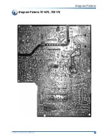
Page 9: ...TC1475 TC2175 TF2139 8 Diagram Pictoric TC1475 TC2175 Diagram Pictoric 6 ...
Page 10: ...TC1475 TC2175 TF2139 9 Diagram Pictoric TF2139 Diagram Pictoric 7 ...
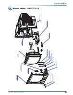
Page 11: ...TC1475 TC2175 TF2139 10 Exploded View TC1475 TC2175 Exploded View 8 ...
Page 12: ...TC1475 TC2175 TF2139 11 Exploded View TF2139 Exploded View 9 ...
Page 28: ......


