Parker Sporlan Subcool Control Installation And Operation Instructions Manual Download Page 7

Bulletin 100-50-5.2 –

 Page 7

These actions are inversely proportional in nature. If the sub-
cooled liquid temperature or Superheat are slow to react to a 
transient system change, then the Proportional may be too low 
and or the Integral value may be too high in value.

Note: Not all refrigeration systems are designed alike. Use 
caution when tuning PID setpoints.

7. Troubleshooting

Recommendations

As with any refrigeration component troubleshooting, actual 
system conditions should be verified with a gauge set and 

calibrated temperature sensor (i.e verify actual superheat, 

subcooling and refrigerant condition). This system infor-

mation is valuable in determining whether it is component 

related or system related. 

For systems or applications that experience light loads on the 
Subcool control circuit, it is important that the Heat exchanger 
and refrigerant lines are sized correctly. This will ensure 
proper oil return and will minimize the effects of oil logging 
in the Heat exchanger. Many Heat exchanger manufacturers 
recommend a hot gas bypass for loads below 50%. Refer to 
the heat exchanger manufacturer’s installation instructions.

Sensors


Failed sensors will trigger an alarm. An alarm code will show 
which sensor is mis-wired, disconnected, or faulty. (See Ap-
pendix G - Alarms and Failsafes

, page 14.) The alarm will 

persist until the problem is corrected. 

Failed temperature sensors

 will generally read extremely 

low or infinite resistance when tested with an ohmmeter. 
Readings should be taken with the sensor disconnected from 
the Subcool Control. A missing or disconnected temperature 
sensor will read 

-60

 on the controller.

Temperature sensor output can be checked by measuring the 
DC voltage across the sensor wire using the tables in Appen-
dix L

, page 19 and Appendix M, page 20.

Since the liquid and suction temperature sensors are identical, 
no alarm will be triggered if the sensors are switched (i.e. liq-
uid sensor on the suction line). 

Severe system damage may 

occur if these two sensor locations are interchanged.

Pressure transducers

 must be installed tight enough to de-

press the valve stem in the fitting. Failure to do so will result 
in erroneous pressure readings and possibly leaks.

Pressure transducers should be tested while connected to 
the controller and powered. Test at the controller terminals. 
Voltage between terminals 34 and 35 should be 4.8 - 5.2 volts 
DC. Voltage between 33 and 34 should be between 0.5 and 
4.5 volts DC. See Table 1 - Pressure Transducer Wire Colors
page 4.

To test the accuracy of the transducer, use a gauge set to 
obtain the actual system pressure. For volts-to-pressure 
conversion, measure the voltage between terminals 33 and 
34. Identify the pressure transducer used and find the correct 
range 

Prng

 in Table 3. 

Substitute the measured voltage (

v

) in the formula in the PSI 

column. The result should be within 3 psi of the actual system 
pressure shown on the gauge set. If not, check transducer for 
proper installation, correct schrader valve, and verify the pres-
sure range identified on the transducer.

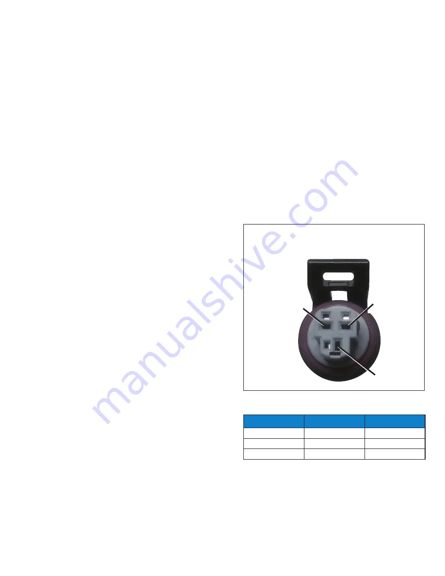
To test the transducer cable, disconnect the cable from the 
transducer and check for 4.8 - 5.2 volts between terminals 

+


and 

 . See Figure 5 - Pressure Sensor Cable.

Table 3 - Pressure Transducer Specifications

LABEL COLOR

Prng

PSI

Green

150

(v-.5) x 37.5

None / Silver

300

(v-.5) x 75

Yellow

500

(v-.5) x 125

Figure 5 - Pressure Sensor Cable

S

+

+ Black
- Green
S White

Summary of Contents for Sporlan Subcool Control

Page 1: ...Bulletin 100 50 5 2 Page 1 Subcool Control Installation and Operation Instructions July 2020 Bulletin 100 50 5 2 Controller v G 1...

Page 2: ...e The user through its own analysis and testing is solely responsible for making the final selection of the system and components and assuring that all performance endurance maintenance safety and war...

Page 3: ...ressure temperature control for most common refrigerants It displays actual leaving liquid temperature superheat suction pressure valve position controller status and alarms It also allows manual cont...

Page 4: ...ivity and you will lose all changes entered 1 Enter the Parameter Menu Press and hold the SELECT knob for 5 seconds Rotate the knob to enter the pass word 111 and press the SELECT knob again 2 To chan...

Page 5: ...ges Ensure superheat does not drop below that described above To exit manual operation mode press encod er knob scroll to ESC and press the knob again After exiting manual mode observe the system for...

Page 6: ...ammed with de fault Proportional Integral Derivative PID settings that will provide efficient control It may be necessary however to fine tune the PID settings in applications where systems experi enc...

Page 7: ...nsor will read 60 on the controller Temperature sensor output can be checked by measuring the DC voltage across the sensor wire using the tables in Appen dix L page 19 and Appendix M page 20 Since the...

Page 8: ...ontrol power Pump down signal ensure Subcool Control expansion valve is not closed Proper system refrigerant charge Liquid line filter clogging or excessive pressure drop Proper Subcooler OffTemperatu...

Page 9: ...adout Description R 22 R 134a R 402A R 404A R 407A R 407C 410A R 410A 417A R 417A R 422A R 422D R 507A R 744 R 245FA R E5 R 438A R 401B 408A R 408A 508A R 508A 508B R 508B 407F R 407F 434A R 434A 444B...

Page 10: ...ional S 4 Status of the Auxiliary Temperature Input Stat Controller Status ALS Controller Alarms APPENDIX C Controller Status DISPLAY DESCRIPTION CooL Subcool On Valve modulating pdn Pumpdown Valve cl...

Page 11: ...448A R 448A 450A R 450A 449A R 449A 452A R 452A 513A R 513A Maximum Valve Capacity 0 to 100 Default is 100 Liquid Proportional Coefficient 0 to 25 5 Default is 1 0 Increase value to increase valve res...

Page 12: ...Units Readout Description Pounds Force Per Square Inch Bars Temperature Units Readout Description Fahrenheit Celsius t4p Temperature SensorType Readout Description typ3 3k typ2 typ2 2k tP10 10k 4 Cho...

Page 13: ...Coefficient LSHi Low Superheat Integral Gain Coefficient The integral gain coefficient to use for the superheat PID loop if the superheat is below 3 degrees F CyCt CycleTime The PID update time StEP...

Page 14: ...ENDIX G Alarms and Failsafes APPENDIX H Technical Specifications ELECTRICAL Supply Voltage 20 26VAC 50 60Hz or 22 26 6VDC Class II input 40VA is recommended for each controller Digital Inputs 0 5VDC M...

Page 15: ...ls Counter Flow Brazed Plate Heat Exchanger Dry Contacts T4 Evap Outlet Temp T1 Liquid Outlet Temp T2 White Signal Green Ground Black 5VDC Black 24V AC DC RS485 White Green Red B Ground A Suction Temp...

Page 16: ...ensors 10 14 inches from the heat exchanger on a free draining hori zontal line 2 Remove all insulation and adhesives at the marked loca tion Using Scotch BriteTM clean the copper line to remove oxide...

Page 17: ...422D 10 R 507A 11 R 744 12 R 245FA 13 R E5 14 R 438A 15 R 401B 16 R 408A 17 R 508A 18 R 508B 19 R 407F 20 R 434A 21 R 444B 22 R 448A 23 R 450A 24 R 449A 25 R 452A 26 R 513A 5 Valve Maximum 0 to 100 6...

Page 18: ...sor Range and Type 15 to 500 PSI 1 01 to 34 47 Bar Maximum Range 4 Saturation Temperature 60 to 150 F 51 1 to 65 6 C 5 Suction Temperature 60 to 125 F 51 1 to 65 6 C 6 Valve Position of Max Stroke 0 t...

Page 19: ...5 0 41 1 837 1 915 5 6 42 1 812 1 889 6 1 43 1 788 1 863 6 7 44 1 763 1 837 7 2 45 1 739 1 812 7 8 46 1 715 1 787 8 3 47 1 691 1 763 8 9 48 1 668 1 738 9 4 49 1 644 1 714 10 0 50 1 621 1 690 10 6 51 1...

Page 20: ...698 5 0 41 2 556 2 663 5 6 42 2 522 2 628 6 1 43 2 489 2 593 6 7 44 2 455 2 558 7 2 45 2 422 2 524 7 8 46 2 389 2 489 8 3 47 2 356 2 455 8 9 48 2 323 2 421 9 4 49 2 290 2 386 10 0 50 2 258 2 353 10 6...

Page 21: ...438 3 540 15 0 59 3 412 3 511 15 6 60 3 383 3 486 16 1 61 3 357 3 456 C F RANGE VDC 16 7 62 3 327 3 427 17 2 63 3 301 3 401 17 8 64 3 271 3 372 18 3 65 3 244 3 346 18 9 66 3 214 3 316 19 4 67 3 183 3...

Page 22: ...een 98 6k Surface Sensor white 952662 230545 230546 230072 230076 230078 230073 952565 Used with or without well 20 ft Surface only 20 ft Air Only 20 ft Surface only 20 ft Surface only 20 ft Surface o...

Page 23: ...ion Author Approved 000 122011 Added Revision History 001 062012 Updated Appendices E I K N Updated Table 2 JH ER 002 112012 Revised as Bulletin JH ER APPENDIX P System Flow Chart Start NO PROCESS Con...

Page 24: ...Parker Hannifin Corporation Sporlan Division 206 Lange Drive Washington MO 63090 USA phone 636 239 1111 fax 636 239 9130 www sporlan com Bulletin 100 50 5 2 72020 2020 Parker Hannifin Corporation...

Reviews: