


Bulletin 100-50-5.2 –
Page 5
suction header to a maximum target value. By default, this
setpoint is high in order to provide full functional subcool
control from the factory. If the
rGhL
is set low, the control-
ler will override traditional subcool control in order to satisfy
the return gas temperature. In this state, the
LoVt
temperature
may fall below the setpoint. To access these parameters see
Section 3 - Setpoint Menu Operation,
page 4.
Manual Valve Position Feature
The Sporlan Subcool Control offers the ability to control
the subcooler expansion valve manually. This feature can be
used in troubleshooting to determine if the expansion valve
responds to an open or closed position signal directly from
the controller. In normal operation, the manual mode should
never be used.
WARNING : Be sure to avoid floodback while using
this feature. Start with the valve in the low position.
Prior to entering manual mode, attach a Sporlan Kelvin II re-
mote display to the RJ-45 port on the side of the Subcool Con-
trol to monitor superheat. This will allow the user to maintain
a minimum superheat while in manual mode by adjusting the
valve position. If the valve is positioned too far open while in
manual mode, superheat will drop and liquid may enter the
suction line. It is always better to start with the valve position
low and work up to a higher position gradually while observ-
ing the superheat value on the remote display. Superheat
should never be allowed to drop below 2°F. If this situation
occurs, reduce valve position and allow system to respond
(superheat should increase).
An alternate way to monitor superheat is to use a gauge set
and a calibrated temperature sensor on the suction line; how-
ever the pressure and temperature will need to be converted to
superheat.
To enter manual mode, press and hold the Select knob, select
111
, scroll to
Spos
and push the knob. See Section 3 - Set-
point Menu Operation
. The valve will start at the current
“original” position. The controller will show percent valve
opening. To verify if the valve is functioning, lower the valve
position by rotating the knob counter-clockwise and note
the change in superheat (increase). From this, increase valve
position slowly and note the change in superheat (decrease). It
may be necessary to allow appropriate time for system to re-
spond to changes. Ensure superheat does not drop below that
described above. To exit manual operation mode, press encod-
er knob, scroll to
ESC
, and press the knob again. After exiting
manual mode, observe the system for proper operation.
WARNING: The controller should never be left
unattended in manual mode.
5. Controller Networking
The Sporlan Subcool Control can communicate with a
MODBUS communication master via RS485 to transfer pro-
cess values and setpoints.
The Subcool Control supports only the RTU transmission
mode. The serial settings are:
•
9600 baud (default), 19200 baud, 38400 baud
•
8 data bits
•
1 stop bit
•
Even parity (default), odd parity, no parity
The Subcool Control supports the ‘Read Input Registers’,
‘Read Holding Register’, ‘Write Single Register’, ‘Read
Multiple Coils’ and ‘Write Single Coil’ function codes. Other
requests will cause an exception response. The Subcool
Control will allow a full and partial block read of the Input
and Holding registers and coils.
Scaling for Celsius / Bar
For better precision, scaling is used for Bar or Celsius units.
PSI and Fahrenheit values are whole numbers and have no
scaling. See Appendix K - MODBUS Memory Map.
Celsius values transferred via MODBUS are 10X. For exam-
ple A value of 45 will be transferred for the Superheat when
the actual Superheat temperature is 4.5°C. Remember this
when changing a setpoint.
Bar values transferred via MODBUS are 100X. A value of 34
will be transferred for the Pressure Sensor Calib. Offset when
the actual pressure is .34 bar. Remember this when changing
a setpoint.
Setup
The Sporlan Subcool Control can be networked to com-
municate process variables back to a master controller. This
information can be used for verifying system performance or
updating individual setpoints via RS-485 and PC interface.
Data can be accessed remotely through the master controller.
For further information on remote monitoring of subcooling,
see corresponding manuals for the master controller.
Prior to establishing the network, each controller must be
assigned a separate address. Refer to Section 3 – Setpoint
Menu Operation
to enter setpoint menu. Once in the Setpoint
menu, scroll to
AddR
and set each controller on the network
with individual addresses. Note: No two controllers can have
the same address. Default address for each controller is ‘1’.
MODBUS Communication Requirements
See Figure 4 - MODBUS Wiring.
Wire Type:
22-24 AWG Universal Twisted Pair
Maximum Number of Network Nodes:
100
Maximum Run Length:
4000 ft
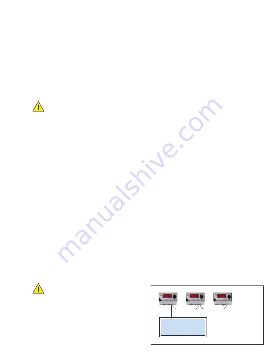
Communication
Master
Figure 3 - Daisy Chain
Network Configuration


