12
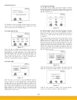
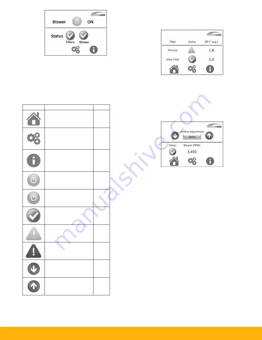
Figure 6
4.3.2 Standard Format
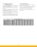
The icon key, Table 3, outlines the various icons that are used on
the screen for various reasons and may indicate status or condi-
tions. The Home, Settings, and Information icons are shown at the
bottom of most screens and will take you directly to their associated
screens. The Status indicator icons are also buttons that will take
you to their associated basic screens as outlined in section 4.3.3.
4.3.3 Basic Screens
Filter Screen:
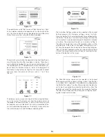
Figure 7
The Filter screen can be displayed by the operator by selecting
the filter status icon on the Home screen shown in Figure 7. The
Filter screen will then be displayed with all available filters. This
screen will display the differential pressure across the filter during
operation.
Blower Screen:
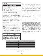
Figure 8
The standard blower screen will display the status of the
blower. If your equipment is equipped with the Auto-Flow option
and it is activated, the Blower screen will look different than that
shown in Figure 8. Refer to section 4.3.4 for additional details.
The only time the blower will shut down is when the blower has
an internal fault. Such faults as: Low line voltage, phase to phase
issues, ground issues, temperature issues, or for a catastrophic
failure. If the blower shuts down, refer to Section 6 for trouble-
shooting.
On the blower screen you are able to adjust the speed of the
blower using one of two different methods. The first adjustment
can be done using the up/down arrows. This adjustment will
achieve a change of +/- 1%. This will increase or decrease the
airflow adjustment by 1% for each touch of the up or down arrows.
The second method of airflow adjustment is to touch the box that
shows the percentage of the airflow. A number pad will be shown
in a pop up screen. You can enter any number between 20 and
100. This will correspond to the percentage of blower capability.
The blower is capable of 4,200 RPM at 100%, 3150 RPM for 75%,
2100 RPM for 50%, and 1050 RPM for 20%. These number are
approximate and may display slightly differently on any given unit.
There is a minimum set point for speed which is 20% for the pur-
poses of the blower design. The SHM may have multiple blowers
incorporated within the system to support performance of the unit
depending on the customer application. All of these blowers will
respond in unison with the SHM’s controller.
ICON
DESC
The Home
you to the
The Sett
take y
custom
sc
The Info
will tak
custom
conta
Blow
Blower is
mode
Statu
Norma
co
Status =
Operat
norm
Statu
Fault co
needs
Decrea
A
Increas
A
CRIPTION
e icon will tak
e home scree
tings icon will
you to the
mer sengs
creen.
ormaon icon
e you to the
mer service
act screen.
wer is ON
s in STANDBY
and is OFF
s = GOOD
al operang
ndion
= WARNING
ting outside
mal ranges
s = FAULT
ondion that
s aenon
se Speed or
Airflow
se Speed or
Airflow
Color
ke
n.
Blue
Blue
Blue
Green
Y
Blue
Green
Yellow
Red
Blue
Blue
TABLE 3
Icon Key
Summary of Contents for SmogHog SHM-C
Page 1: ...SMOG HOG Media Mist Collector Owner s Manual Models SHM C SHM F...
Page 6: ...Page intentionally left blank...
Page 8: ...4 FIGURE 1B SHM Equipment Description 61 10113 FIGURE 1A SHM Equipment Description...
Page 13: ...9 61 10126 FIGURE 4 Remote Panel Touchscreen Connection...
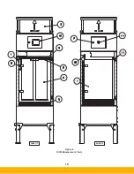
Page 23: ...19 Figure 6 SHM Replacement Parts SHM 11C SHM 11F...
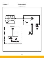
Page 24: ...20 APPENDIX A1 WIRING DIAGRAMS BASIC CONTROLS 04 001682...
Page 25: ...21 REMOTE PANEL BASIC CONTROLS 04 001799 APPENDIX A2...
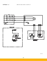
Page 26: ...22 ONE BLOWER AND CONTROLS 04 001695 APPENDIX A3...
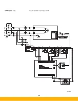
Page 27: ...23 TWO BLOWER AND CONTROLS 04 001696 APPENDIX A4...
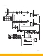
Page 28: ...24 THREE BLOWER AND CONTROLS 04 001697 APPENDIX A5...
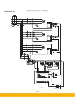
Page 29: ...25 REMOTE PANEL TOUCH CONTROLS 04 001802 APPENDIX A6...
Page 30: ...26 ONE BLOWER AND REMOTE CONTROLS 04 001798 APPENDIX A7...
Page 31: ...27 TWO BLOWER AND REMOTE CONTROLS 04 001797 APPENDIX A8...
Page 32: ...28 THREE BLOWER AND REMOTE CONTROLS 04 001796 APPENDIX A9...
Page 33: ...29 575 480 TRANSFORMER 04 001717 APPENDIX A10...
Page 36: ...32...
Page 37: ...33...


