


In the event the valve is left disassembled for any length of time,
protecting the components is essential . Place the components
in a polyethylene bag or apply a rust protection agent, such as
refrigerant oil .
Contractors need to follow a WPS (Welding Procedure
Specifcation) for all welding . The procedure must be qualifed and
the welder doing the weld qualifed to perform that procedure .
The codes applicable to the welding of socket weld valves require
that the pipe be inserted into the socket until bottomed against
the stop . The pipe is then to be backed out approximately
1
⁄
16
of an inch before welding . Use of welding rings is optional, but
recommended for butt weld valves . They help alignment, control
gap for full penetration welding, and reduce welding debris entry .
Note:
When welding carbon steel and stainless steel, the welded
joint should be painted to prevent galvanic corrosion .
Socket welding, where allowed, is the preferred connection . This
connection helps to reduce the amount of welding debris in the
piping system .
Remove welding debris and any dirt from the pipes and valve body
before reassembling the valve .
Before putting valves into service, all pipe connections, valve seats,
bonnet seals, and stem seals should be tested for leaks at pressure
levels called for in the appropriate codes .
Installation
All valves are packed for a maximum protection . Unpack carefully .
Check the carton to make sure all items are unpacked . Save the
enclosed instruction for the installer and eventual user .
Do not remove the protective coverings from the inlet and outlet of
the valve until the valve is ready to be installed . Protect the inside
of the valve from dirt and chips before and during installation .
i
Caution
All personnel working on valves must be qualifed
to work on refrigeration systems . If there are any
questions contact Parker Refrigerating Specialties
before proceeding with the work .
The valve should be installed in a location where it is easily
accessible for adjustment and maintenance . The location should
be such that the valve can not be easily damaged by material
handing equipment . When it is necessary to insulate the valve, the
insulation should be installed to provide access for adjustment
and maintenance . Do not insulate solenoid coils . Proper indicating
gauges should be installed to be easily visible to the operating
engineer for system checks and adjustment purposes .
The preferred mounting method for the S8VS series is in the
upright horizontal position .
The valve must be installed with the
arrow pointing in the direction of flow for the valve to function
properly . Prior to welding, protect the inside of the valve body
from welding debris and dirt .
Bulletin 10-02
6
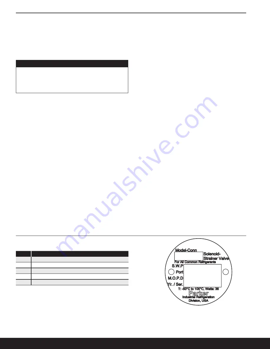
Item
Description
1
Model - Connection Size
2
Safe Working Pressure
3
Port Size
4
Maximum Operating Pressure Differential
5
Year / Serial Number
Nameplate Information
Table 2:
S8VS/S8ST Nameplate Identification
Figure 4:
S8VS/S8ST Nameplate
1
5
4
3
2


