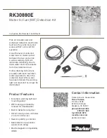
Specifications
Port Thread Size
1/2"-20 UNF
Housing
Glass-filled Nylon
Volts DC
12 or 24
Ohm (trigger threshold)
47K
Ambient Fuel Temperature
-40
o
to +250
o
F (-40
o
to +121
o
C)
RK30880E
Disconnect the Negative terminal
from the battery to avoid the
potential hazard of electrical
shock. Run the wires in protected
locations and avoid hot surfaces
and places that could pinch or
rub on the wires.
1. Lubricate o-ring on water
probe with silicone lube or
clean motor oil, then install into
collection bowl. Tighten probe
body snugly by hand only.
2. Connect
BLACK
wire on
connector assembly to ground,
RED
wire to +12/24 vdc, and
YELLOW
wire to either wire of
supplied lamp (use a supplied
butt splice connector). This will
send a ground (-) signal once
water is detected.
Note: The yellow output wire
sends a ground signal (-) when
water is detected. This signal
can only support a 1 amp load
so the provided lamp is ideal.
Should you want this signal to
trigger a warning device that
draws more than 1 amp, use
a relay (customer supplied)
to drive the device. The
yellow wire (ground signal)
should be attached to the coil
ground terminal of the relay.
Once water is detected, the
ground signal will activate the
coil, thus closing the power
contacts to drive your device
(horn, buzzer, etc.).
3. Use loose black wire (supplied
with lamp) and butt splice
connector to connect other
side of lamp to 1 amp fuse,
then to +12/24 vdc.
4. Mount plastic under-dash
bracket and install lamp into
bracket hole or drill a 0.50˝
(12.7 mm) diameter hole in
panel and mount lamp directly
to panel.
5. Use cable ties to secure any
loose wires. Reconnect positive
battery terminal.
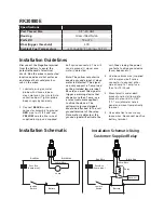
Installation Guidelines
Installation Schematic
Red Wire
Black Wire
Yellow Wire
Fuse Box
(2 amp max.)
Lamp
+
-
+
-
Battery
Ignition
Switch
Red Wire
Black Wire
Yellow Wire
Fuse Box
(2 amp max.)
Relay
+
-
+
-
Battery
Ignition
Switch
Installation Schematic Using
Customer-Supplied Relay
+
-
Horn, etc.


