


192-011004N5 PSD1-S Short Description 2017-08
192-011004N5 DOC-0002-01-R014
14.08.17 09:41
7
(20)
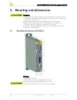
2.6.4.
Special dangers
Danger!
Due to movable machine parts and high voltages, the device can pose a lethal
danger. Danger of electric shock in the case of non-respect of the following
instructions. The device corresponds to DIN EN 61800-3, i.e. it is subject to limited
sale. The device can emit disturbances in certain local environments. In this case,
the user is liable to take suitable measures.
•
Check that all live terminals are secured against contact. Perilous voltage levels
of up to 850V occur.
•
Do not bypass power direct current.
CAUTION: Risk of Electric Shock
Caution - Risk of Electric Shock!
Before wiring or loosening electrical connections please observe the
following:
•
Risk of electric shock, disconnect power before removing cover resp. disconnect
the devices from the mains supply.
•
Caution!
Dangerous electrical voltage even after turning off the intermediate
capacitors:
Up to
3 minutes
after switching off mains supply, dangerous voltages may
still be present.
Please check that no voltages are present (<50 V) at the output terminals DC+
and DC- (X63/3 & X63/5).
•
The device must be permanently grounded due to high earth leakage currents.
The leakage current is greater than 3.5 mA.
•
The drive motor must be grounded with a suitable protective lead.
•
The devices are equipped with high voltage DC capacitor.After switching off the
supply voltage, it may take up to 3 minutes (with additional capacity modules it
may take up to 30 minutes) to discharge the capacitors.
Danger of electric shock in case of non respect.
•
Do never perform resistance tests with elevated voltages (over 690V) on the wiring
without separating the circuit to be tested from the drive.
•
Please exchange devices only in currentless state and, in an axis system, only in a
defined original state.
•
If the axis controller is replaced, it is absolutely necessary to transfer the
configuration determining the correct operation of the drive to the device before
the device is put into operation. Depending on the operation mode, a machine zero
run will be necessary.
•
The device contains electrostatically sensitive components. Please heed the
electrostatic protection measures while working at/with the device as well as
during installation and maintenance.
2.6.5.
Cautionary Markings
Ignoring of the following instructions will result in personal injury or material
damage.
•
The heat disispator can reach very high temperatures (>70°C)
•
Do never perform resistance tests with elevated voltages (over 690V) on the wiring
without separating the circuit to be tested from the drive.
•
Please exchange devices only in currentless state and, in an axis system, only in a
defined original state.