8
Tool Circuit Requirements
Model Sizes
PG06
PG07
PG08
Displacement
in
3
(cm
3
)
84.8
(1,390)
118.5
(1,942)
211
(3,458)
Required Oil Flow
gpm
(liters/minute)
2-7
(8-28)
3-10
(12-39)
5-18
(21-70)
Port Connections*
SAE
6
6
8
Hydraulic Circuit
Min. Hose Tube Size
Whip Hose Size
in
(mm)
in
(mm)
1/2
(12)
3/8
(10)
5/8
(16)
3/8
(10)
5/8
(16)
3/8
(10)
Hydraulic Pressures
Cross Port Relief Valve Pressure (opening)
Cross Port Relief Valve Pressure (closing)
Circuit Pressure
Maximum Circuit Back Pressure
1,000-1,500 psi
3,200-3,300 psi
3,650-3,750 psi
580 psi
(70-103 bar)
(220-230 bar)
(250-260 bar)
(40 bar)
* 3-10 second open/close time
Hydraulic Requirements and Plumbing
Hydraulic Requirements
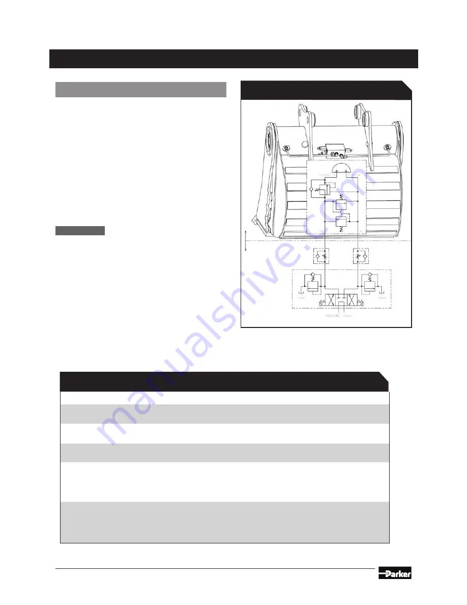
The Typical PowerGrip Circuit Chart and the Tool
Circuit Requirements Table (shown on this page)
illustrate the control circuit requirements for the
PowerGrip. The hydraulic pressures and flow
requirements must be observed or damage to the
actuator can occur.
The installer of the PowerGrip is responsible
for selecting control circuits that are compatible
with the excavator and meet the tool circuit
requirements. Helac can be contacted for
additional control circuits and methods for
controlling the PowerGrip.
NOTICE
PowerGrips are equipped with
a standard pressure control/
load lock manifold welded to the
bucket shell.
Refer to the Suggested Hose Routings Diagram
on Page 11 for the recommended routings.
Typical PowerGrip Circuit
INSTALLATION AND MOUNTING


