K3.1.114o Manual NitroFlow Mobile
- 16 -
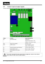
5.6
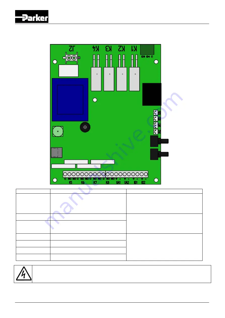
Connect input and output signals
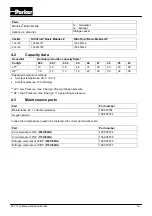
Input and output signals can be connected to the terminal strip on the printed circuit board.
Clamp Function
Input/output
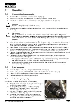
signals
ID1 Remote
start/stop
Digital input
Nominal input current: 10 mA
Voltage: internal power supply
UA1 Oxygen
concentration
Analogue output
Input impedance to reach
0 mA – 20 mA: 200 Ohm
UA2 Outlet
pressure
K5
Start stop signal to external booster
Volt Free Relay Contacts
Switch voltage: 48V AC/DC
Switch current: 1A AC/DC
K6
General alarm (nc/no)
K7
General alarm (nc/no) (=K6)
K8 Spare
The circuits connected to the relay contacts must be supplied by a fused or current limited
power supply. All cables must be double insulated.
Summary of Contents for NitroFlow Basic Series
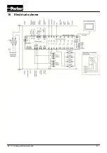
Page 32: ...K3 1 114o Manual NitroFlow Mobile 31 10 Electrical scheme...
Page 33: ...K3 1 114o Manual NitroFlow Mobile 32 11 Declaration of Conformity...
Page 34: ...NOTES...
Page 35: ......