isysNet EtherNet/IP Adapter, Series A (PSSCENA)
E104P
3
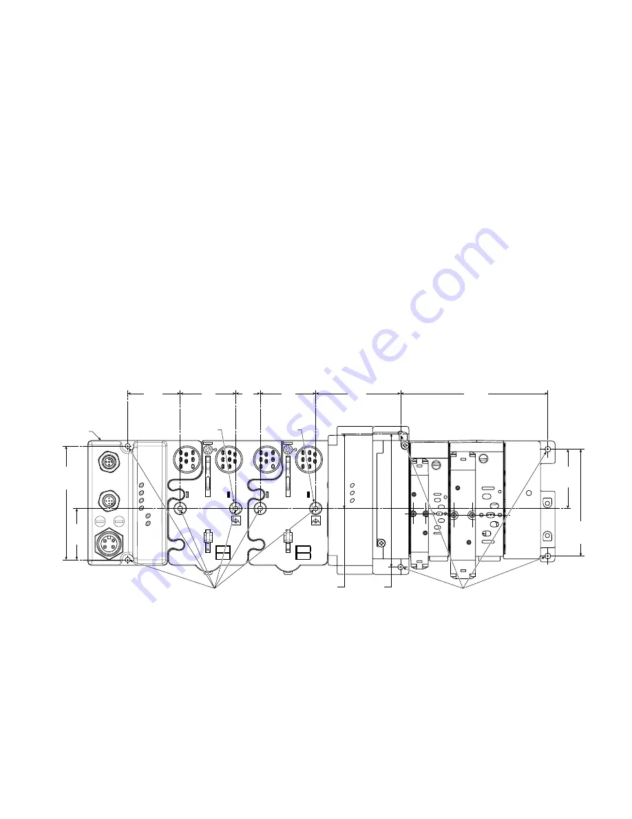
Mount the Adapter and I/O Base
To mount the adapter on a wall or panel, use the screw holes
provided in the adapter.
A mounting illustration for the adapter with I/O bases is shown
below.
Inches
(mm)
Adapter
2.0
(50)
2.0
(50)
1.9
(47.2)
4.02
(102)
1.81
(46)
4.32
(109.8)
5.39
(137.0)
Drill and Tap
for M4 Screw
I/O Module
Ground
2.39
(60.7)
3.02
(76.6)
3.13
(79.4)
5.98*
(151.9)
0.87
(22)
Drill and Tap
for M6 Screw
I/O Module
Ground
Install the Mounting Base as Follows:
1. Lay out the required points as shown above in the drilling
dimension drawing.
2. Drill the necessary holes for #8 (M4) machine or self-tapping
screws.
3. Mount the adapter using #8 (M4) screws.
4. Ground the system using the ground lug connection in the I/O
base. (The ground lug connection is also a mounting hole.)
Before You Begin
To effectively use your adapter, note the following considerations.
Determine Compatibility
If using the adapter with an Allen-Bradley 1756-ENBT module or
1788-ENBT module, use the following required firmware versions
for these bridge modules:
• 1756-ENBT firmware version 2.3 or greater
• 1788-ENBT firmware version 1.33 or greater
If you use the BootP Utility to assign IP addresses to the adapter,
use version 2.3.2 or greater.
Understanding Messaging
Class 3 (Explicit Message) requests through the adapter to a specific
I/O module may not always receive a response from the I/O module.
In the case where the I/O module does not reply to the request, the
adapter responds with an error code indicating a time-out.
Establish I/O Connections
When you power up an isysNet I/O system and establish I/O
connections, the outputs transition to the Idle state, applying Idle
state data before going to RUN mode. This occurs even when the
controller making the connection is already in RUN mode.
Configure Autobaud
The adapter cannot reconfigure an I/O module that you previously
configured to operate at a fixed baud rate. When you reuse an
isysNet I/O module from another isysNet I/O system, configure the
module to autobaud before using it with the adapter.
Open Configuration Method
For using isysNet EtherNet/IP Adapters without RSNetWorx™ or
RSLogix™ 5000, refer to document “User Guide: Configuration of
the isysNet™ Pneumatics Platform using Explicit Messaging", which
is available at www.parker.com/pneu/isysnet.
* Depending on the type and number of manifolds, this dimension
may vary. Refer to Catalog 0600P-# for additional information.
Grounding
Each isysNet base has two mounting holes, with the one on the
right being the means to ground each module. Each module must
be grounded.


