Bulletin 2751-001-M1/USA
Service Manual
HGA Hydraguide™
Hydraulics
Parker Hannifin Corporation
Hydraulic Pump/Motor Division
Greeneville, Tennessee
20
Assembly Procedure
15. Assemble spacer (15) over valve spool (22), against
spring washer (14). If so constructed, the inside lip end
of spacer must be toward the spring washer. Place
assembly, spool end first, into housing (25). Caution:
Avoid applying side forces to the spool which would
cause binding of the closely fitted assembly.
Note: If neither the input shaft (16) or upper cover (7)
are replaced, the original shims (9) may be reused.
However, if in the inspection of parts, damage is
found to the shims, discard these shims and replace
with new parts of equal thickness.
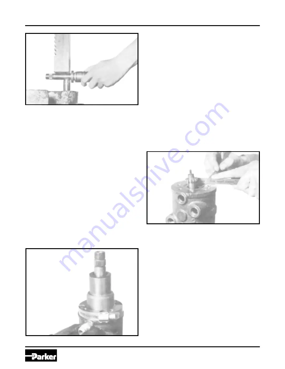
16a. Place shims on top of the thrust washer (11). Coat seal
(8) with clean grease and place in upper cover (7)
counterbore. Assemble upper cover onto input shaft (16)
and rotate to align punch marks previously made during
disassembly. Note: If a new upper cover is used no
angular orientation is required. However, it is
necessary to align the upper cover (7) and housing
(25). Replace with screws, finger tight, and then use a
pilot ring or a worm drive type hose clamp tightened
around the upper cover flange and the body pilot
diameter to achieve the required alignment. Now tighten
screws to 18-22 ft. lbs. torque. (See Figure HGA-20).
NOTE: If any of the input shaft (16), housing and
spool, torsion bar or upper cover (7) have been
replaced, the following procedure for checking and
shim adjustment must be used.
16b. Re-assemble as in “a” above using the required new
parts. After torquing the four screws (6) revolve unit in
vise so that the input shaft is pointing downward. In
order to determine that the unit is shimmed correctly,
the drive link (30) must be in its proper position. To do
this, grasp the input shaft (16), pull downward, and
prevent rotation. Engage drive link splines in spool (22)
and rotate to position spool essentially flush with end of
housing (25). Remove drive link and orient drive link
slot to engage torsion bar needle roller (21) and insert
drive link. Observe relationship of spool end to body.
The valve spool must protrude .020 ± .0025 from the
adjacent counterbore surface. If within spec. no
additional shimming required. If not within .0025, add or
remove shims (9) until this requirement is satisfied
repeating assembling steps as outlined in “a” above.
(See Figure HGA-21).
16c. The correct shimming must be checked on the vehicle
or on a suitable hydraulic test stand. The amount of
steering effort required to steer the vehicle when the
vehicle is at rest on dry pavement must be equal within
three inch pounds. For example: if twenty-one inch
pounds is required to steer to the right, not less than
eighteen or more than twenty-four inch pounds should
be required to steer to the left.
If a test stand is available to place a load between
cylinder ports in the same manner as on the vehicle, a
test stand should be used. Add shims to increase
steering efforts in a left turn, subtract shims to
increase steering effort in a right turn.
17. With the drive link (30) installed as described above,
assemble two assembly posts into the housing (25) as
shown in Figure HGA-22. These assembly posts can be
made by simply cutting the heads off of two bolts similar
to the special bolts (39).
Figure HGA-20
Figure HGA-19
Figure HGA-21


